



Paveway II Delivery Profiles - Buddy-Lasing - Low Altitude - Intervisibility Planning (22/25)
This article is the practical follow-up to the previous "introduction to intervisibility" article. There we established the geometric idea of line-of-sight and the simple nomogram method for converting obstacle height and distance into a required LOS angle. Now we can put that tool to work: step-by-step, we’ll plan a full low-level laser attack from the first climb to final bomb impact in the exact sequence you’ll need to do it during the planning phase.
But why discuss it in the buddy-lasing section only? In principle the same LOS calculations apply to self-lasing, and you could have had this chapter earlier. But buddy-lasing is the best method for the lowest-profile employment: the designator aircraft remains further and can accept the climb and the exposure necessary to acquire target while the shooter remains lower and as long as possible, better concealed. In a self-lasing profile, the shooter would probably have to climb sooner, denying the potential for "low level" attack.
You will see that at first glance the process looks complex: there are many distances, angles and obstacles to check, but once you've understood it, you'll see that the method is fundamentally simple and logical!
Once you have understood this process, you'll be able to replicate the most demanding attacks, like the low level AS-30L strikes shown on the introduction video. This historical footage comes from Desert Storm, and the full story can be read there (original page in French). Obviously, in that case, intervisibility over the sea is not a factor... But the very same missions have been carried out over the land, and then the full planning process becomes mandatory!
I. The four phases
Any low level LASER attack can be split into four phases, that we'll describe below in reverse chronological order.
I.1 - The "LASER" phase
The LASER phase is the end of the chain: the designator's pod is stable on the aimpoint and the decision to release is executed. During the egress, the LOS is rotating as you steer the aircraft towers the release axis, so new obstacles that were irrelevant on the approach axis may become important in the final degrees. The LASER phase demands the most careful obstacle check during preparation and a conservative attitude during execution.
The LASER phase is defined by two parameters: the distance to target (D3), at which you are expected to be at bomb release, and the LOS offset that will occur during the egress turn, typically 40° to 45° above 5 Nm, but potentially up to 60° if you are closer to target.
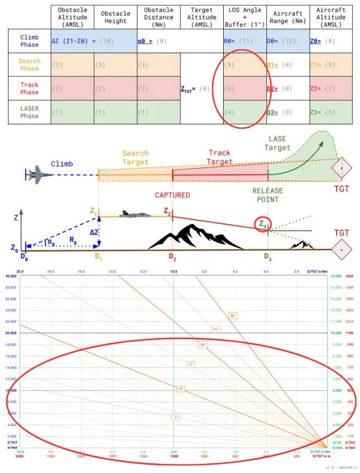
This LOS offset angle will be used to identify the area in which obstacle study has to be performed, in green on the above picture. The goal here will be to determine the altitude Z3 at which you should be at the beginning of the LASER phase.
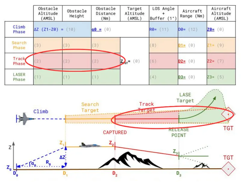
I.2 - The "track" phase
The track phase is the short window in which in which you lock your pod on target and you commit to the final attack. It is defined by a single reference point, defined by the distance at which you expect the sensor to be captured and holding steady (D2). We want to determine the altitude you will occupy at that moment (Z2).
To determine D2, you need to plan for a captured track long enough to stabilise the picture, correct any small aiming errors, and do the radio comms with the shooter: roughly thirty seconds is a good default, with anything under fifteen seconds becoming tactically risky. Knowing your planned groundspeed, you convert that capture time into the appropriate D2.
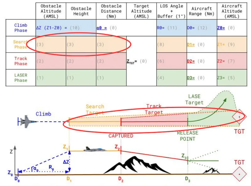
I.3 - The "search" phase
The search phase begins at the distance D1 where you start actively using your TGP: automatically slew the pod on known target location, adjust brightness, choose IR or visual bandwidth, and zoom as required. The aim is to find the visual features that characterize your target area without a doubt, in order to be able to pinpoint its location, and be able to VID it before the "Captured" distance at D2.
During search you fly level at the planned search altitude (Z1). The goal is to be able to spend time in the cockpit in order to look for large visual cues, like roads, relief, or distinctive buildings. If the aimpoint is obvious in an open field the search may be short, but if the aimpoint sits inside a cluttered area the search might be long and methodical. Plan for a measured window of time: long enough to positively identify the target and nearby verticals but short enough to avoid unnecessary exposure while you remain at the search altitude.
As for D2, the search phase length will be transformed into a distance using the planned ground speed, and the aim will be to determine Z1 at D1.
I.4 - The "climb" phase
The climb is the phase where you transition from the very low level combat navigation phase, possibly as low as 150' AGL, to the search altitude (Z1) where you'll start focusing on the TGP. It happens before you even touch the pod, and it's purely an aircraft-management problem, not a sensor problem. You pick a climb profile that the airframe can sustain, given your current load and desired speed.
In practice this means choosing a climb angle that is realistic for the aircraft: with a potentially high drag configuration, and near to maximum sustained speed without afterburner, you may be able to climb at modest angles only, possibly 5° to 10° maximum. Obviously, using the AB during a few second will expedite the climb, but will cost you in fuel and might reveal you to IR sensors.
II. Step by step planning
II.1 - Starting Parameters
Before you touch the nomograph or open CombatFlite, you must reduce the problem to a handful of fixed inputs. Treat these as the mission “givens”: they are the assumptions the rest of your planning will be built on.
II.1.1 - Target elevation (Z TGT)
First, note the elevation of the aimpoint. It's either given in your ETF (Electronic Target Folder), or you have to get it from a map, either in the mission editor or the F10 view, or on any mission planning tool with elevation data. Be conservative if the map data are uncertain.
This altitude will be the reference from which you measure obstacle heights and compute required aircraft altitudes.
II.1.2 - Standoff at weapon release (D3)
Choose the attack profile you plan to fly, and determine the distance D3 at the start of the lasing maneuver.
We will later study a standard "Wedge" formation profile, with D3 = 6.0 Nm away from the target. If you don't have any better profile, you can use this distance as a reference.
If you do a self-lasing profile, we have seen earlier that a loft or toss bombing will bring you around 4.0 Nm from target at bomb release.
II.1.3 - Track and search windows (D2 and D1)
Decide how long you want the pod captured before release and how long you want for the initial search. These times are human and sensor choices: they reflect how confident you expect to be in target recognition and how stable you want the TGP before committing. Convert those times into D2 and D1 using an assumed ground speed.
For now, pick a nominal capture window of 30" and a search window between 15" and 30" depending on target complexity. Once you gain experience, you'll be able to refine those figures for each target configuration.
II.1.4 - Nominal climb angle (α₀)
Choose the climb geometry you will use to get from low-level transit to search altitude. As discussed earlier, 5° is a reasonable value for all configurations, and up to 10° can be used if you have enough energy margins. Values above 10° will probably require afterburner to maintain speed.
II.1.5 - Lateral buffer and navigation assumption
As this stage, you should also decide how much lateral corridor you will protect on the axis. If your navigation is waypoint-driven and precise, and with a modern aircraft, you can use a smaller buffer (1 NM). If you are navigating visually, in formation without exact waypoints, double that buffer. This choice determines which obstacles enter the list and how conservative your LOS angles must be.
With the mission givens locked (Z TGT, D3/D2/D1, α₀ and lateral buffer), the next step is the map work. We will turn the map into an obstacle picture and convert vertical heights into the LOS angles that will control our altitudes.
II.2 - Obstacle study and LOS angles
With the main planning parameters defined, you can now start transforming the theory seen previously into actionable figures. The goal of this step is simple: identify what stands between your laser and the target, quantify it, and turn it into altitudes you can actually fly.
This is where maps, DEMs, and the nomograph all come together.
II.2.1 - Obstacles study
For every obstacle you consider, record three basic numbers on your table: the horizontal distance to the target, the top altitude (above sea level), or the bottom altitude and obstacle height if the top altitude is unknown. For the obstacle height, you will often need to make a rough estimate: for example, a 5-storey building is roughly 15 meters high, and a large tree can be 25 meters high.
The three items above let you compute the effective height above the target itself and can expose hidden problems like a tall object standing in a depression or a short object on a rise.
II.2.1.1 - Close-in work
Start within the immediate vicinity of the target: here the LOS can vary quickly, and man-made objects or vegetation dominate. Walk the full egress sector visually and note every antenna, chimney, tree line, water tower, or high rise building within a few hundred metres to a kilometre. Mark each entry with top and bottom altitudes. If one of those values is unknown, assume conservatively and flag it as “assumed.” Since this close study also covers the whole LASER egress sector (typically 40°–60° depending on release range).
II.2.1.2 - Mid- and far-field work
Once close objects are catalogued, move outward. Use your 1:100,000 chart for the local relief then extend to 1:250,000–1:500,000 scales (or DEMs) for larger terrain features that can produce smaller but still controlling angles at distance. For these farther obstacles you can tolerate slightly lower confidence. Don't forget that any off-axis feature inside your lateral buffer is relevant.
Make a distinction between obstacle before the desired "Captured" point, and after. Typically, you might have to fly over a mountain to spot the target, and be able to descend behind once the target is in sight.
II.2.2 - LOS calculations
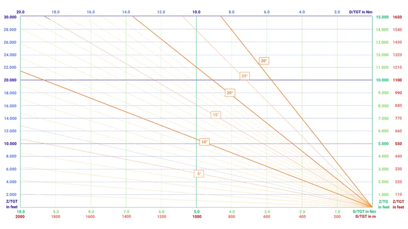
Work each obstacle through the nomograph to get its LOS angle as seen from the target at their respective distances. It's a trial-and-error method: assess roughly which obstacle seems to be the most factor, and compare the next obstacles to this one.
From those per-obstacle LOS readings identify the single controlling obstacle for each phase: the one producing the largest LOS angle at D1, the one at D2, and the one at D3. These maxima are your controlling angles. Once identified, add the tactical margin: +1° to the controlling LOS angle to account for global flight inaccuracies.
II.2.3 - Z calculations
Take previous LOS values you computed and use the nomograph to translate them into the aircraft altitudes Z1, Z2 and Z3 that you must occupy at D1, D2 and D3.
Read directly from the nomograph (angle → altitude at range) or use your preferred conversion method. Record Z1/Z2/Z3 and note the obstacle that controlled each value (so that you know if you can descend once the obstacle has been crossed.
If any Z is impractically high given the tactical situation, it means that the chosen attack axis has to be reworked!
II.2.4 - D0 calculation
Using the required search altitude Z1 and your starting altitude Z0, find the vertical ΔZ = Z1 − Z0 and use the nomograph to convert that ΔZ and your chosen climb angle α₀ into the horizontal climb length required. In practice you can use simple mental calculation rules like 5° = 2Nm / 1,000 ft.
Add that climb length to D1 and you get D0, the point along the inbound axis where you must start the climb.
Note: be late at D0 and you’ll be short all the way through search and capture. Mark D0 clearly on your brief and on the navigation log. Ideally try to find a distinctive visual reference to mark it on the ground.
Conclusion
This planning method turns what looks like an intimidating accumulation of distances, angles and map checks into a logical and repeatable workflow. From a few mission givens (target elevation, D3, planned capture/search windows, climb angle and lateral buffer) you precisely build a full vertical profile. Those numbers belong on the kneeboard so you can quickly re-check them before the attack and have a clear mental picture of the run.
Two operational reminders before you go fly it:
first, many obstacle problems relax as you close: range shrinks and the LOS angle increases, so features that were controlling at long range often cease to be once you pass them. That can permit a measured descent during the track phase. If, however, you discover an error in your calculations, stick to your briefed altitude and be patient: the target will often reveal itself a few seconds later as geometry changes.
second, the moment you enter the target’s LOS you also change your exposure picture: radar and optical threats that could not see you at low altitude may now. This reciprocal geometry is part of the risk trade: the designator accepts that exposure so the shooter can remain lower and better concealed.
If you follow the sequence (i.e. define the givens, catalogue obstacles, convert to LOS, translate to Zs, then to D0) the low-level laser run becomes both very precise and powerful. And also importantly, as you'll see it at debriefing, it's very rewarding! Being able to anticipate how the attack run will develop is the true reasons of the planning phase.
In the next articles we will study two standard low-level profiles. While the loft/toss will directly exploit what you’ve learned here, you'll see that the pop-up profile will use the same methods only during its initial phase.