




Paveway II Delivery Profiles - Buddy-Lasing - Low Altitude - Intervisibility (21/25)
It's now time to enter into the final stage of the Paveway II Delivery Profiles series. After examining the standard attack profiles (level, dive, loft, toss, and pop-up) and the buddy lasing profiles at medium and high altitude, we can now address the most demanding environment: low-level buddy lasing. It is the most complex because the geometry is unforgiving, since at low altitude, even small obstacles can hide the target, it is the most difficult to fly, close to the ground while manipulating a targeting pod, and there is no automated tool to help you during the planning phase.
We will start with a first discussion about the crucial question of intervisibility, that has not been introduced yet, because in general, at medium and high altitude, intervisibility if not a concern. However, now that we are trying to fly as low as possible, it will become a key element, and there's no point going any further before you understand it.
I. The concept of intervisibility.
I.1 - Vocabulary
When we plan low-level buddy lasing, the geometry vocabulary matters. Below are the precise meanings that are used in this series so there is no later ambiguity.
Line of sight (LOS): it's the pure geometric straight line between two points in space. If nothing physically intersects that straight line, the LOS is clear. This is the basic geometric test we apply to laser propagation.
Intervisibility: it's the mutual LOS between two points, and each can see the other. In practice we often compute a one-way LOS (designator → target or vice versa). The terms LOS and intervisibility will be used without practical distinction.
Visual line of sight (VLOS): it's the LOS plus the human/optical limits of seeing. It takes into account atmospheric visibility, contrast, haze, darkness, and the resolving power of the sensor/tube in use. A LOS can be geometrically clear but VLOS may fail (night, fog).
Radar line of sight (RLOS): LOS adapted to radiofrequency propagation. RLOS calculations add antenna heights, radar horizon effects and refraction (standard atmospheric bending), so RLOS often extends slightly beyond pure geometric LOS for small antenna heights but can be shorter or longer depending on ducting/refraction.
For low-level buddy lasing we only need geometric intervisibility of the laser beam. We do not consider atmospheric visibility (VLOS) nor radio propagation (RLOS). The laser beam is effectively a geometric straight line at the tactical ranges we use: the single remaining question is whether terrain or vertical objects intersect that line.
I.2 - Flat-Earth simplification
We will ignore Earth curvature in the trigonometry formulas used for manual LOS calculations. That raises two practical questions:
How large is the curvature error at the ranges we care about?
When should curvature be considered?
If we use the standard practical approximation for Earth curvature expressed as vertical drop below a local tangent: Drop (feet) ≈ 0.883 × (distance in nautical miles)².
From that, the curvature introduces a tiny change in the LOS angle. Because the effect scales with the square of range, but the angle error scales roughly linearly with range. Practically speaking, the curvature represents around 100 ft at 10 Nm, which is negligible: those errors are far smaller than the practical uncertainties you will have in obstacle height data, track keeping, and well inside the 1° tactical safety buffer we apply later.
That's why for low-level buddy lasing in the ranges that matter, neglecting curvature is entirely acceptable and keeps the method simple and usable in the planning phase.
II. Intervisibility calculation
Now that the concept of intervisibility is clear, we can move on to the practical question: how do we actually calculate it?
There are two main ways to determine whether your designating aircraft will have a clear line of sight to the target along a given axis of attack:
by using computer planning tools, such as CombatFlite, which can provide a quick, terrain-based intervisibility;
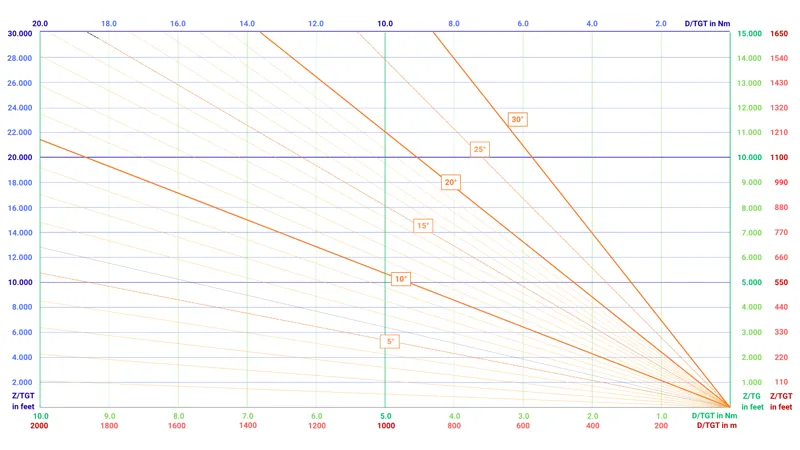
by performing a manual calculation with a simple graphical calculator (the intervisibility nomogram), which allows you to make all the calculations with just a map, verify results or work in areas where the software data is unavailable.
Both methods aim to answer the same question: from a given range, what is the minimum altitude required for the LASER to see the target?
The automated tool can seem faster, but it's also limited by the quality of its terrain database, and typically it won’t include man-made obstacles such as antennas, buildings, or trees. The manual method is slower but more flexible, and often the only way to account for those missing elements close to the target.
II.1 - Using planning tools like CombatFlite
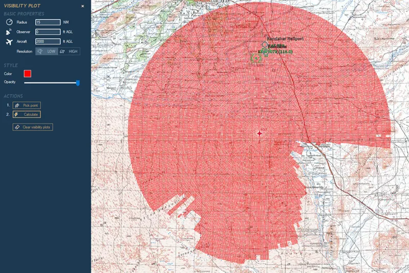
When time and data are available, a mission-planning package such as CombatFlite is the fastest way to generate an intervisibility check and a vertical elevation profile along the planned arrival axis. While it cannot replace local knowledge or manual verification, it greatly reduces the amount of analysis you need to perform by hand and provides an excellent starting point for terrain evaluation.
To perform this analysis, you must first define a few key elements: the target location, which serves as the reference point, the desired approach axis or bearing, which allows you to generate an elevation profile along that track, and either the planned aircraft altitude for a profile view or the aircraft height above the ground if you intend to produce an intervisibility footprint.
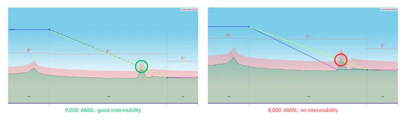
The tool will then deliver several useful outputs. It can display a detailed terrain elevation profile between your aircraft position and the target, allowing you to visualize any potential obstructions along the line of sight.
It can also generate an intervisibility footprint that shows, for a given aircraft height above ground level, which parts of the terrain remain visible to the sensor or designator. Finally, CombatFlite allows you to export these profiles, maps, and visibility areas as images suitable for inclusion in your mission brief.
However, there are some important limitations to keep in mind. The software cannot produce an intervisibility footprint for a fixed aircraft altitude above sea level, only for a height above the terrain.
It also does not compute the minimum line-of-sight angle or the corresponding minimum flight altitude required to maintain visibility on the target. These values must still be determined manually.
Additionally, the underlying digital elevation model (DEM) used by CombatFlite often excludes man-made structures and vegetation. Antennas, chimneys, high-rise buildings, and tree lines are not represented in the terrain data. As a result, any “clear” intervisibility indication within roughly two to three nautical miles of the target should be treated as conditional until you verify the local area through imagery or direct observation.
This is because small, nearby verticals have an outsized effect on line-of-sight: a 50-metre building 450 ft from the target creates an LOS angle of about 20°, the same angular blockage as an ~11,075 ft mountain 5 NM away, while a 20-metre tree line 260 ft out produces ≈14° and a 6-metre greenhouse 90 ft away gives ≈12°.
Put simply, objects measured in metres and located only a few hundred feet from the aim point can block the laser as effectively as multi-thousand-foot terrain at standoff ranges. That is why DEM-only checks are insufficient: mission planning must include a close inspection of the immediate target area (high rise buildings, antennas, chimneys, tall trees, etc...) and a manual LOS check otherwise you will either over-commit to a blocked axis or be forced into last-minute changes in axis, climb profile, or standoff.
As a conclusion, it quickly becomes clear that while CombatFlite is an efficient tool for visualizing intervisibility, it does not provide a complete solution. It tells you whether the line of sight is clear or obstructed, but not the minimum altitude required to achieve that visibility. Moreover, it cannot account for small but significant obstacles located near the target area.
II.2 - Manual calculation with a graphical calculator
When software is unavailable or when you need to account for man-made obstacles that DEMs omit, the manual graphical method gives you a reliable, repeatable way to convert obstacle height and distance into the line-of-sight angle and, from that angle, into a required aircraft altitude at any chosen standoff. As you will see, the method is quick and simple.
The nomogram used in this method is a simple graphical angle calculator: a two-axis chart (distance on the horizontal, obstacle height on the vertical) with diagonal angle lines so that a single plotted point immediately gives the LOS angle. In practice the nomogram lets you skip trigonometry: place an obstacle’s height and its distance to the target on the chart and read the corresponding line-of-sight angle where the point intersects the diagonal grid.
Begin by collecting the basic map data: pin the target, draw the arrival axis, and walk that line to identify vertical obstacles inside your planning radius, typically out to 15 - 20 Nm, but pay particular attention to anything within a few hundred metres. For each obstacle record two values: its height above the local ground (in feet) and its horizontal distance from the target along the arrival axis (in nautical miles or kilometres).
If you use the nomogram, place the obstacle point on the chart by matching its distance on the horizontal axis and its height on the vertical axis: where the plotted point intersects the diagonal angle grid read the LOS angle in degrees.
Once you have the obstacle’s LOS angle, repeat the process for every obstacle along the arrival line and then select the maximum angle; this maximum is the geometric constraint you must beat to obtain an unobstructed laser path from that axis. Add a tactical buffer (the standard used here will be one degree) to the maximum LOS angle to create the required LOS angle for planning.
Convert the required LOS angle into a required aircraft altitude at a chosen distance by reading it directly on the graph.
Note: This chart can be used at any scale. The relationship between height, distance, and LOS angle is purely geometric, so all values scale linearly. For example, the 20 NM axis is exactly twice the 10 NM one; the same applies to metric distances: the LOS angle at 4 km is twice that at 2 km for the same height-to-distance ratio. In practice, you can read any range scale simply by multiplying or dividing both height and distance proportionally.
A few practical shortcuts will speed the process without losing efficiency. First, only the handful of obstacles that produce the highest angles matter: distant low objects can be ignored. Second, always assume conservative heights when you lack precise data for near-target features. Finally, record an obstacle table in your planning material (obstacle ID, distance, height, LOS angle, required aircraft altitude at various points) so that you can precisely explain everyone what obstacles are expected during the briefing. But we will review the practical planning method for Paveway II in details later.
Conclusion
This article introduced the basics of low-level buddy lasing intervisibility. I encourage you to start studying the graphical method to determine LOS angle: it's really a simple tool once you understand its principle.
One of the key point that I'd like you to remember, is that even small obstacles close to the target can block the laser as effectively as large mountains several miles away. Automated tools like CombatFlite will help, but they cannot replace manual verification of the near-target area.
In the next articles, we’ll apply this method to a complete Paveway II buddy-lasing plan, then move on to the two tactical profiles: loft/toss and pop-up.