
Standalone Is Coming…
The Standalone ECU Tuner is almost ready.
We are still testing every system, fixing the remaining bugs and polishing the final details, but the biggest part of the development is already complete. The first release is coming in the next few days.
Below is the full list of currently implemented features:
🖥️ ECU, PROJECTS AND CONTROLS
• Complete standalone ECU interface directly in the game.
• ECU tune and physical vehicle hardware are stored separately.
• NORMAL, SPORT and OVERBOOST ECU presets.
• Save and load complete projects.
• Save the current calibration directly to the ECU.
• Saved and unsaved change indication.
• Renameable ECU workspaces.
• Full, top, bottom and corner compact display modes.
• Metric and imperial unit systems.
• AFR or lambda display depending on the selected fuel.
• Context information panel for every major function.
• Status bar with active systems, warnings and faults.
• ECU Light with the exact fault reason shown on hover.
📊 LIVE DATA, DIAGNOSTICS AND DATALOGGER
• Fully configurable Live Data cards.
• Custom selection of displayed channels.
• Adjustable Live Data card frame colors.
• Adjustable blue, normal and red value zones.
• The same selected data in full and compact modes.
• Live RPM, TPS, MAP, lambda, pressure and temperature display.
• Live requested and actual ignition timing.
• Live requested and actual camshaft position.
• Live injector duty, fuel cut and EGO correction.
• Live electrical demand, voltage and alternator output.
• Live oil pressure and oil temperature.
• Live IAT, CLT, EGT and charge temperature.
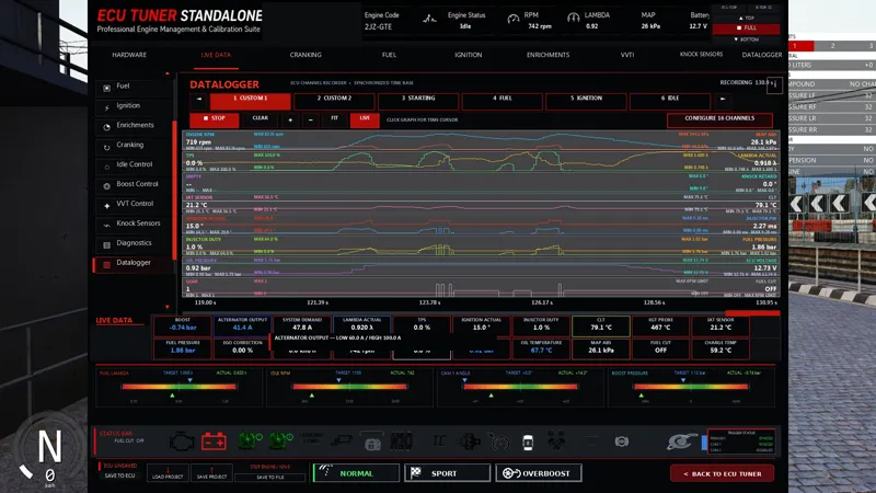
• Configurable multi-channel datalogger.
• Multiple custom datalogger pages.
• Zoom, scrolling and a vertical log cursor.
• Values of all channels under the cursor.
• Minimum and maximum values in the visible log range.
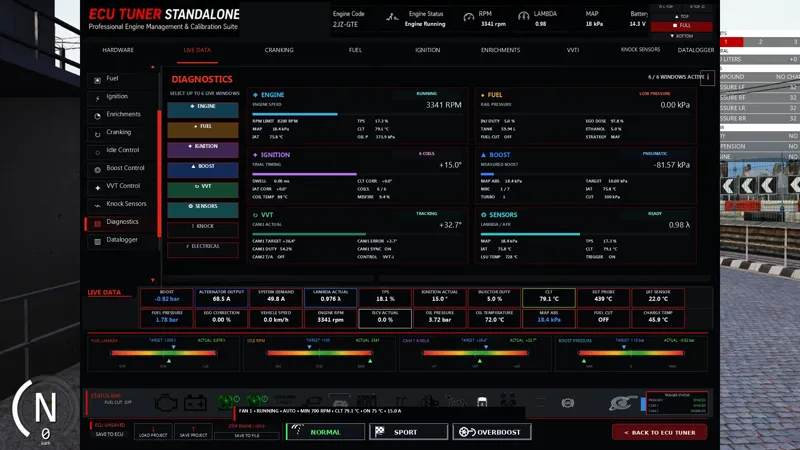
• Trigger, synchronization and cam sensor diagnostics.
• Diagnostics for individual cylinder ignition events.
• Boost control, VVT, knock and fuel cut diagnostics.
⛽ FUEL AND INJECTION
• MAF fuel strategy.
• Speed Density fuel strategy.
• Alpha-N fuel strategy.
• Combined MAF/MAP strategies.
• 16×16 Target Lambda map.
• 16×16 load-based fuel correction map.
• IAT fuel correction.
• Charge Temperature correction.
• Warm-up enrichment based on engine temperature.
• Afterstart enrichment after the engine catches.
• Acceleration enrichment during rapid throttle application.
• Flex-fuel corrections based on ethanol content.
• Sequential, semi-sequential and batch injection.
• Individual trim for all six injectors.
• Adjustable injector flow rate.
• Injector dead time calibration based on voltage.
• Physical difference between requested and actually delivered fuel.
• Real effect of fuel pressure on injector flow.
• Fuel temperature and density simulation.
• Fuel rail volume and pressure pulsation simulation.
• Adjustable mechanical and electronic fuel pressure regulators.
• Multiple fuel pumps with different flow limits.
• Closed-loop EGO correction with PID control.
• Adjustable conditions for EGO correction operation.
• Injector duty warning.
• Adjustable Injector Duty Fuel Cut.
• Minimum one-second hard cut when the injector duty limit is exceeded.
• Thermal overload and damage for individual injectors.
• Possibility of complete injector failure.
• RPM-based fuel cut.
• MAP/overboost fuel cut.
• Deceleration fuel cut during engine braking.
• Adjustable activation and recovery conditions for fuel cut.
• Fuel consumption calculation.
• Real ethanol content and octane rating based on the fuel mixture in the tank.
🛢️ GAS STATION AND FLEX FUEL
• Refueling with multiple fuel types.
• Mixing E10 gasoline, premium gasoline and E85.
• Automatic calculation of final ethanol content.
• Automatic calculation of final octane rating.
• Display of the amount of each fuel in the tank.
• Refueling is blocked while the vehicle is moving.
• Refueling stops immediately if the car starts moving.
• The tank can only be emptied while the vehicle is stationary.
🔑 STARTING AND AFTERSTART
• Physical starter powered by the battery.
• Real effect of battery voltage on cranking speed.
• Separate cranking fuel and ignition maps.
• Prime pulse before cranking.
• CLT-based cranking fuel.
• CLT-based cranking ignition.
• Flex-fuel cranking correction based on ethanol content.
• Intake wall fuel film simulation.
• Flooded engine simulation.
• Anti-flood starting with the throttle pressed.
• Individual cylinders catch progressively.
• Audible individual combustion events and “puffs” during starting.
• Rough-start behavior caused by incorrect fuel, weak spark or synchronization problems.
• Afterstart phase after every genuine engine start.
• Adjustable Cranking Threshold.
• Optional start without CAM sync, depending on ECU configuration.
• Bump-starting through a selected gear and clutch engagement.
• A violent bump-start can make the timing system jump one or two teeth.
• Jumped timing permanently changes cam timing until the engine is repaired.
• Engine sound is audible immediately from the first cylinders that catch.
⚙️ IDLE CONTROL
• PWM ISCV idle control.
• Open-loop idle control.
• Closed-loop idle PID.
• Separate Cranking Duty map.
• Afterstart Duty Addition map.
• Idle duty correction based on RPM error.
• Adjustable idle target.
• Adjustable TPS threshold for idle mode.
• Adjustable maximum idle RPM.
• Adjustable valve position outside idle mode.
• Simulated mechanical PWM valve deadband.
• DBW idle-control mode for supported hardware.
• Real RPM drop while fuel cut is active.
⚡ IGNITION
• 16×16 main ignition map.
• Battery-voltage-based dwell map.
• Afterstart ignition lock.
• Correct 1-5-3-6-2-4 firing order.
• Individual ignition events for all six cylinders.
• Real effect of low voltage on coil charging.
• Weak spark and misfire simulation.
• Individual cylinder disable through injector trim.
• Selection of different ignition coils.
• Selection of different spark plugs.
• Adjustable plug type, heat range and gap.
• Coils and spark plugs can only be changed with the engine stopped and ignition switched off.
• Strobe timing check for trigger and ignition alignment.
🎧 KNOCK SENSORS AND KNOCK CONTROL
• Two physical knock sensors for the 2JZ block.
• Sensor frequency, sensitivity, mounting and health simulation.
• 16×16 knock threshold map.
• Knock detection only inside adjustable RPM/MAP/TPS windows.
• Individual cylinder knock detection.
• Knock event counter for each cylinder.
• Individual ignition retard based on knock intensity and repetition.
• Global retard when multiple cylinders knock.
• Adjustable maximum retard.
• Gradual ignition recovery after knock ends.
• Optional fuel enrichment after knock detection.
• Stronger protection for repeated or severe knock.
• Knock icon in the Status Bar flashes when knock is detected.
• Live diagnostics for both knock sensors.
• Live retard, enrichment and affected-cylinder diagnostics.
🌀 BOOST CONTROL AND TURBO PHYSICS
• Independent physical turbo simulation without native Assetto Corsa boost.
• Exhaust energy drives the turbine and turbo shaft.
• The compressor fills the real charge-pipe and intercooler volume.
• MAP results from airflow, throttle position and engine air demand.
• Turbo lag, inertia and shaft coast-down simulation.
• Wastegate flow and exhaust backpressure simulation.
• Blow-off valve and compressor surge simulation.
• Turbo overspeed and turbo damage simulation.
• Compressor outlet air temperature simulation.
• Intercooler pressure-drop simulation.
• Intercooler heat-soak simulation.
• Selection of multiple turbo hardware options.
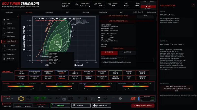
• OEM 2JZ-GTE sequential twin CT12B turbo system.
• Only the first turbo operates at low RPM.
• The second turbo is pre-spooled before being connected.
• The second turbo exhaust valve opens before its intake valve.
• The second turbo joins according to RPM and load, approximately in the 3000–4000 RPM range.
• A small natural softening of boost can occur during the transition to both turbos.
• MBC mode with mechanically fixed boost control.
• MAC mode with ECU boost control.
• Open-loop boost control.
• Closed-loop boost PID.
• Boost Target 1 map.
• Boost Target 2 / Overboost map.
• Base Solenoid Duty map.
• Duty Error Correction map.
• Gear-based boost correction.
• Vehicle-speed-based boost correction.
• Ethanol-based boost correction.
• IAT-based boost correction.
• CLT-based boost correction.
• Knock and fuel-pressure-based boost protection.
• Adjustable wastegate spring.
• Pneumatic wastegate to EWG conversion only in the Engine Workshop.
• Compressor map with a live operating point, shaft-speed line, efficiency zone and trace recording.
• The compressor map is diagnostic only and does not change physical engine boost.
⏱️ VVT, CAMSHAFTS AND TIMING SYSTEM
• NON-VVT mode.
• VVT-i mode for the intake camshaft.
• DUAL VVT-i mode for both intake and exhaust camshafts.
• Separate CAM1 target map.
• Separate CAM2 target map.
• Closed-loop cam-position PID.
• Live target and actual camshaft position.
• Physical phaser response instead of an instant jump to target.
• Cam position affects cylinder filling, dynamic compression ratio, overlap and knock risk.
• Selection of different camshaft profiles.
• Real effect of cam duration and lift on engine behavior.
• Choice of fixed, adjustable or VVT cam gears.
• Separate intake and exhaust cam gear selection.
• Each cam gear can be adjusted from −2 to +2 teeth.
• Timing alignment check against a crank timing reference.
• Physical installation timer for cam gears, tensioner and timing belt.
• Incorrect timing changes engine behavior and valve timing.
📡 SENSORS AND TRIGGERS
• MAP sensors with different pressure ranges.
• TPS calibration and filtering.
• MAF sensor with frequency and airflow simulation.
• CLT sensor with a fallback value during failure.
• IAT sensor with a fallback value during failure.
• Flex-fuel sensor for ethanol content and fuel temperature.
• EGT sensor with thermal response delay.
• Bosch LSU 4.2 and 4.9 wideband lambda sensors.
• Adjustable wideband heater mode.
• Wideband damage caused by incorrect use.
• Calibration error, dropout and complete lambda-sensor failure.
• Persistent temperature-sensor damage.
• 2JZ 36-2 primary trigger.
• CAM1 intake sync/VVT sensor.
• CAM2 exhaust sensor for Dual VVT-i and backup synchronization.
• Adjustable trigger edges, filters and synchronization conditions.
• Diagnostic trigger status for CRANK, CAM1 and CAM2.
🔋 ELECTRICAL SYSTEM
• Physical battery with capacity, state of charge and internal resistance.
• Multiple battery sizes.
• Battery discharges with active electrical loads even when the engine is off.
• Accelerated battery charging option in the Hardware menu.
• Physical alternator with multiple maximum-current ratings.
• Multiple alternator output options.
• Alternator current depends on RPM and electrical load.
• System voltage reacts to actual current demand.
• Starter electrical load.
• Ignition-coil electrical load.
• Injector electrical load.
• Fuel-pump electrical load.
• Radiator-fan electrical load.
• Fan startup inrush current.
• Brake-light electrical load.
• Brake lights draw current even with the ignition switched off.
• Electrical load from other active systems and solenoids.
• Warning for an undersized alternator or low system voltage.
🌡️ COOLING, OIL AND TEMPERATURES
• Coolant-temperature simulation.
• One or two independent radiator fans.
• Adjustable fan size.
• Separate activation temperature for each fan.
• Adjustable fan hysteresis.
• Adjustable minimum RPM for automatic fan operation.
• AUTO, FORCE ON and FORCE OFF for each fan.
• FORCE ON works with the engine stopped when ignition switch 2 is active.
• Real fan electrical demand.
• Separate sound for running radiator fans.
• Oil-temperature simulation.
• Oil-pressure simulation.
• Engine-oil viscosity and type selection.
• Engine-oil quantity simulation.
• Oil wear and degradation simulation.
• Fuel dilution of the oil during poor combustion and rich operation.
• Cylinder fuel wash during extremely rich operation.
• Oil-cooler hardware selection.
🔥 COMBUSTION AND ENGINE BEHAVIOR
• Separate combustion events for all six cylinders.
• Individual lambda for each cylinder.
• Individual fuel dose for each cylinder.
• Individual ignition timing for each cylinder.
• Individual combustion quality and completeness.
• Lean misfire.
• Rich misfire.
• Misfire caused by weak spark or damaged components.
• Unburned fuel affects EGT, sound and engine behavior.
• Power is produced from the air, fuel and combustion actually captured by the model.
• Static and dynamic compression ratio based on the physical engine build.
• IAT, CLT, ethanol, octane and ignition timing affect knock risk.
• Exhaust backpressure affects filling, EGT and power.
• Physical RPM drop based on friction, pumping losses and accessory load.
• Engine sound reacts to individual combustion events and engine condition.
🔧 ENGINE HARDWARE
• Physical hardware is stored separately for each car.
• Loading an ECU preset does not change installed hardware.
• Most external hardware can only be changed at 0 RPM with ignition OFF.
• Internal engine parts can only be changed in the Engine Workshop.
• Alternator selection.
• Battery selection.
• Turbo selection.
• Intercooler selection.
• Injector selection.
• Fuel-pump selection.
• Fuel-pressure-regulator selection.
• Wastegate-spring selection.
• MBC or MAC boost-hardware selection.
• Throttle-body selection.
• Adjustable throttle-body base opening.
• Camshaft-stage selection.
• Ignition-coil selection.
• Spark-plug selection.
• Wet or dry nitrous-system selection.
• Nitrous-shot and solenoid-type selection.
• Weight-reduction stages.
• Downpipe/exhaust-bypass hardware selection.
• Oil and cooling hardware selection.
• Every Hardware item states whether it can be changed with the ignition off or only inside the Workshop.
🛠️ ENGINE WORKSHOP
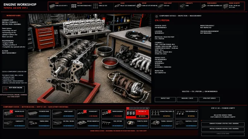
• Complete interactive Engine Workshop.
• Step-by-step full engine disassembly.
• Step-by-step full engine assembly.
• Timed service operations.
• Separate visual renders for individual disassembly stages.
• Final render of the fully disassembled engine with the crankshaft removed.
• Combined step for draining oil and coolant and disconnecting the engine wiring harness.
• Throttle-body removal.
• Fuel rail and injector removal.
• Intake-manifold removal.
• Turbo and exhaust removal.
• Ignition/coil-cover assembly removal.
• Accessory-drive removal.
• Timing-drive removal.
• Camshaft and valve-cover removal.
• Cylinder-head removal.
• Piston, connecting-rod and bearing removal.
• Crankshaft and main-bearing removal.
• Reassembly in the correct order.
• Component cards for all major engine parts.
• Part Service with a large render of the selected component.
• Switch between removed components without closing Part Service.
• Separate Inspect Part function.
• Separate Measure / Check function.
• Replacement-part selection through a direct catalog.
• Every part change requires separate confirmation.
• Irreversible machining requires separate confirmation.
• The original part can be reinstalled without mandatory inspection.
• Bulk INSPECT and MEASURE through the ALL selection.
• Individual piston, connecting-rod and bearing selection by cylinder.
• Pistons and connecting rods are installed only as complete six-piece sets.
• Rod bearings are serviced individually by cylinder.
• Main bearings are serviced individually by position.
• Individual R1–R6 connecting-rod journal selection.
• Individual M1–M7 main-journal selection.
• Individual inspection and measurement of every journal.
• Journal Machining for the selected journal.
• Polishing or grinding a journal to STD, −0.025 or −0.050 mm.
• Grinding is performed only after confirmation.
• Bearing size must match its corresponding journal.
• The engine will not allow crankshaft installation with incorrect bearings.
• Selection of OEM, nitrided or billet crankshafts.
• Separate cylinder-head selection.
• Separate head-gasket selection.
• NON-VVT, VVT-i or Dual VVT-i head selection.
• Individual inspection and measurement of each cylinder bore.
• Honing of all six cylinders.
• Block boring to 86.50 or 87.00 mm.
• Full-block decking.
• OEM 86 mm pistons cannot be used after boring the block to 87 mm.
• A compatible forged-piston selection opens automatically for an 87 mm block.
• Damage inspection for the head, block, pistons, connecting rods, bearings and crankshaft.
• Measurement of diameters, clearances, taper, ovality, warpage and wear.
• Separate intake and exhaust timing-gear selection.
• Timing adjustment against the crank reference.
• Physical installation of timing gears, belt and tensioner.
• Coils and spark plugs are only removed and reinstalled in the Workshop; their type is selected in Hardware.
• An unchanged wastegate spring remains installed after assembly.
• Pneumatic wastegate to EWG conversion only in the Workshop.
• BUY NEW ENGINE instantly replaces the entire physical engine with a new one.
• BUY NEW ENGINE keeps the current ECU tune.
• Returning to the ECU is blocked until the engine is fully assembled or replaced.
⚠️ DAMAGE, WEAR AND FAILURES
• Persistent physical engine and hardware state for each individual car.
• Piston wear.
• Piston ring-land and crown damage.
• Piston-skirt scuffing and cylinder-wall damage.
• Connecting-rod wear and damage.
• Individual rod-bearing damage.
• Individual main-bearing damage.
• Individual crankshaft-journal damage.
• Block, cylinder-bore and deck damage.
• Cylinder-head, valve-seat and head-gasket damage.
• Timing-system damage and skipped teeth.
• Incorrect bearing clearances reduce oil pressure and damage the engine.
• Seizure can increase friction, reduce power or stop the engine.
• High EGT and detonation increase the risk of damage.
• Both lean and excessively rich mixtures can cause misfire and damage.
• Turbo overload can accelerate wear or damage the turbo.
• Sensors can degrade, drop out or fail completely.
• The ECU uses adjustable fallback values for selected sensor failures.
• ECU Light remains illuminated for at least two seconds after a serious event is detected.
➕ ADDITIONAL FEATURES
• Simulated alternator and engine-accessory load.
• Simulated power-steering-pump load.
• Wet/dry nitrous hardware and multiple shot levels.
• Multiple weight-reduction stages.
• Physical connection between installed hardware, ECU calibration and resulting engine behavior.
• Most faults and damage can be diagnosed through Live Data, status displays or the Engine Workshop.
• Loading another ECU project or preset does not overwrite physical hardware.
• All major hardware changes and machining operations require the correct engine state and explicit user confirmation.
This list reflects the current development build. Some details may still be adjusted during final testing and bug fixing before release.
Comments (4)
Sheesh like u said I think I'm gonna stick to Power Stages
Bro are u human? Crazy work looking forward to use this
🤤🤤
holy ***...