






















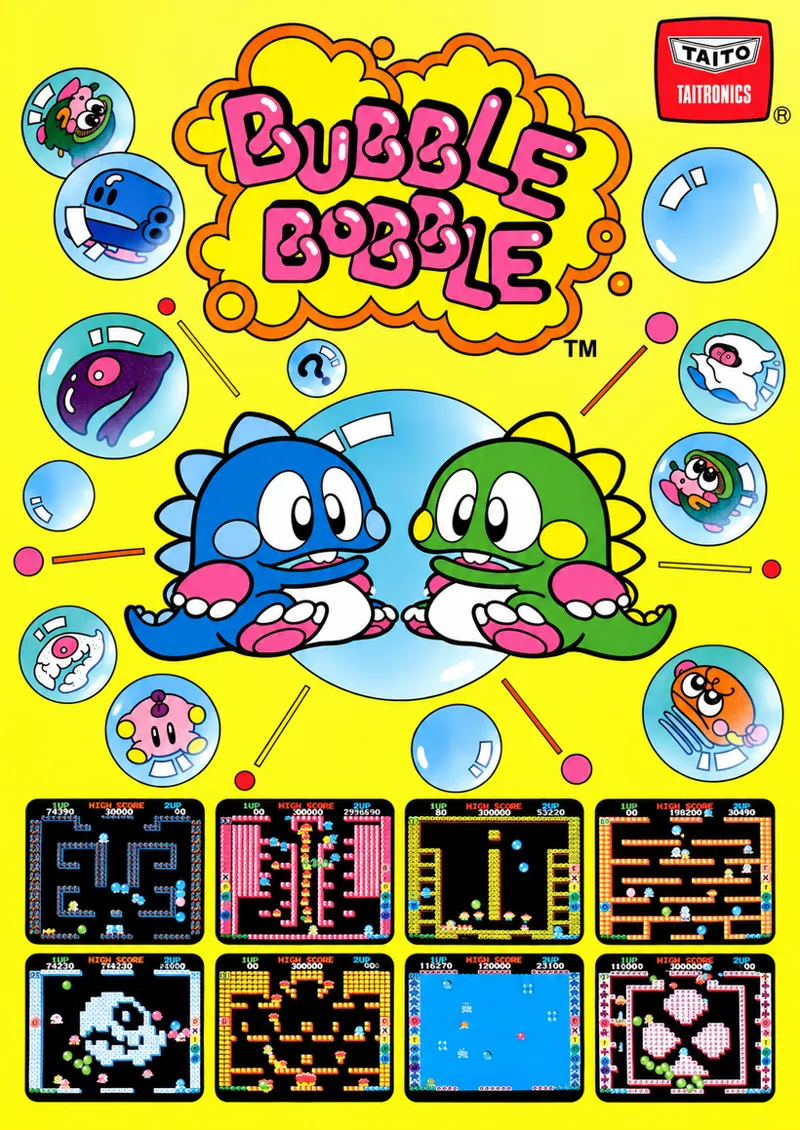


Coin-Op Collection Presents: Bubble Bobble (Taito A78)
Today's beta release for the Analogue Pocket and MiSTerFPGA platforms is Bubble Bobble, a 1986 Taito arcade game built on the A78 architecture. Bubble Bobble is a single-screen platform game where Bub and Bob, two brothers turned into bubble-blowing dragons, work their way down 100 rounds of a cave to rescue their girlfriends.
The game was developed at Taito's Central Research Laboratory and designed by Fukio Mitsuji. The hardware is split across two boards. The CPU board carries three Z80s, a protection microcontroller labeled PS4, a YM2203 and a YM3526, while the video board carries the master clock, the raster counters and the entire graphics pipeline. There is no tilemap present; the whole picture is built from an object list the video board walks once per line.
This post covers a technical overview of Bubble Bobble, the work the board required, and the game itself.
Licensing:
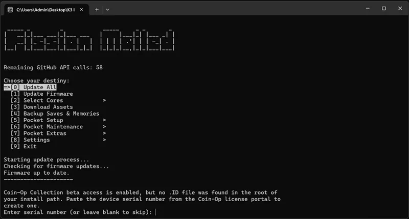
Bubble Bobble is distributed through the Coin-Op Collection licensing portal, which serves both MiSTerFPGA and Pocket from the same dashboard. Patrons need to register their device and generate a key before launching the core. Registration uses the ChipID utility, which shows your device's Hardware ID as a QR code you scan with your phone, and each account covers one MiSTer and one Pocket by default. Step-by-step instructions and the FAQ are available on the Help page.
Keys are tied to your Patreon subscription and are generated on the 2nd of each month, while yearly subscribers' keys run until the end of their subscription. On MiSTerFPGA, Update All downloads and renews the key automatically for RetroAccount members. On the Analogue Pocket, pupdate downloads and renews the key automatically on every update run.
The core is a beta release. On MiSTerFPGA, automatic key installation through Update All requires a RetroAccount membership. As a RetroAccount member, register your MiSTer on the licensing portal, then log in from the Update All Settings Screen and link your FPGA ID from the Account section. Update All installs the key and renews it automatically.
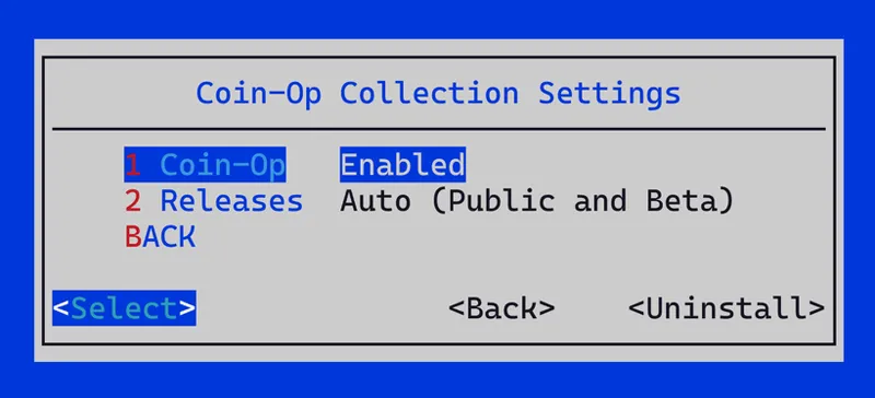
The Coin-Op Collection submenu has options for Public, Beta and Alpha releases, following your Patreon tier by default and replacing the downloader.ini edit from earlier posts. The full walkthrough is in the Update All 2.11 post here. If you are not a RetroAccount member, you can manually set your tier.
For the Analogue Pocket, pupdate fetches the key for you. Turn on the Coin-Op Collection auto-fetch option under Accounts in pupdate's settings. pupdate reads your Hardware ID from the .ID file at the root of the SD card, downloads coinop.key on every update run and copies it to each core that needs it. If there is no .ID file, pupdate asks for the 16-character Hardware ID shown on the portal and saves the file once the key downloads.
The MRA files for this release carry a [CoC] ending, such as Bubble Bobble (Japan, Ver 0.1) [CoC], because more than one core for this game is available on MiSTerFPGA, and the ending keeps ours apart from the others in the arcade menu. The Analogue Pocket does individual entries per core and the naming requirement is not necessary.
Overview:
Bubble Bobble runs on Taito's A78 hardware (CPU board K1100191A / J1100078A, video board J1100070A), driven by a Zilog Z80B at 6 MHz working through a fixed window at the bottom of the map and a banked window above it paged over four banks. A second Z80B at 6 MHz shares the main processor's work RAM, and a Z80A at 3 MHz handles sound, taking commands from the main processor through a pair of latches.
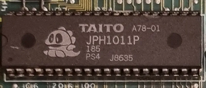
A protection microcontroller sits alongside them, a socketed Motorola MC6801U4 marked A78-01 and silkscreened PS4, running from its own 4 MHz crystal. It reads every player input and both DIP switch banks and shares a RAM with the main processor. Three PAL devices on the CPU board handle the address decode, the work RAM arbitration and the microcontroller's shared RAM sequencing.
The audio is generated by a YM2203 and a YM3526, both at 3 MHz and each feeding its own YM3014 DAC, through TL074 unity followers and an MB3731 bridge-tied power amplifier. The two FM legs and the YM2203's SSG are summed passively at a single node. Audio output is mono.
Every clock on the board except the microcontroller's descends from a single 24 MHz oscillator on the video board, halved to 12 MHz and again to 6 MHz for the pixel clock and both Z80Bs, and halved once more to 3 MHz for the sound Z80A and both FM chips. The microcontroller's 4 MHz crystal is the only other frequency source on the board.
The video system outputs 256x224 in a horizontal orientation. There is no CRTC on this PCB; the raster comes out of the counter chain itself, giving a 6 MHz pixel clock with an HTOTAL of 384 and a VTOTAL of 264. Each 64.00 µs line splits into 256 active pixels (42.67 µs), a 51 pixel front porch (8.50 µs), a 29 pixel sync (4.83 µs) and a 48 pixel back porch (8.00 µs) for a 15.625 kHz horizontal rate, while each 16.90 ms frame splits into 224 active lines (14.34 ms), a 16 line front porch (1.02 ms), an 8 line sync (0.51 ms) and a 16 line back porch (1.02 ms) for a 59.1856 Hz vertical rate. Sync is composite only. These timings are taken from the schematic and PCB.
Graphics are sprites and nothing else. There is no tilemap RAM and no dedicated object RAM; the object list and the tile entries it points at share 8 KB of V-RAM, which the CPU writes a byte at a time and the video board reads sixteen bits wide. A pair of 74LS283 adders work out each object's row against the current line, the A71-25, the board's only PROM, decides how that object's tiles are laid out, and the finished pixels land in one of two line buffers that change hands every line. Characters are 8x8 at 4bpp out of 384 KB of ROM across twelve 27256 devices.
The palette is RAM rather than PROM, 256 entries of 16 bits, and fifteen of those bits reach three Taito PC040DA hybrid DACs, five bits per gun, with the sixteenth bit connected to nothing. That gives 256 entries in 15-bit RGB.
Development Challenges:
Main CPU and Sub CPU:
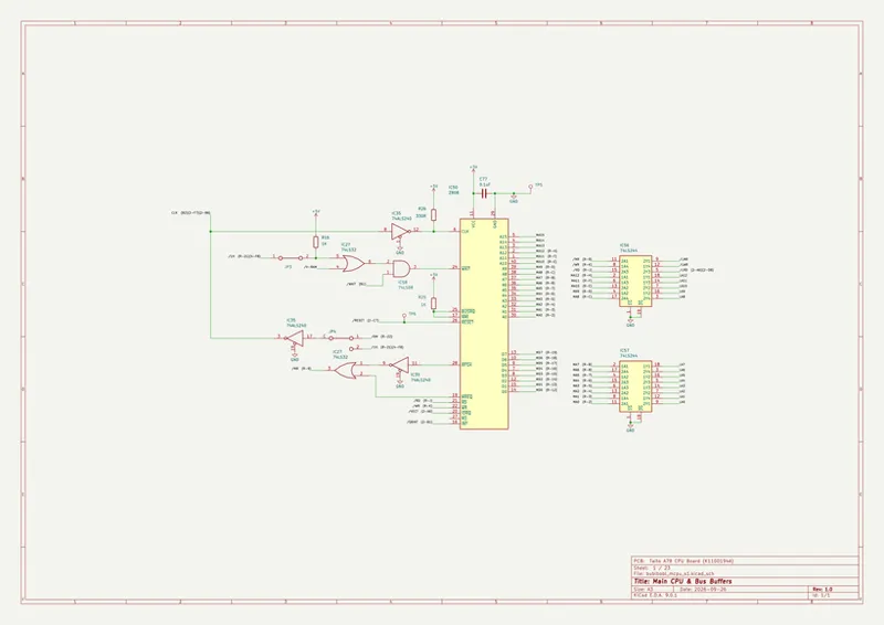
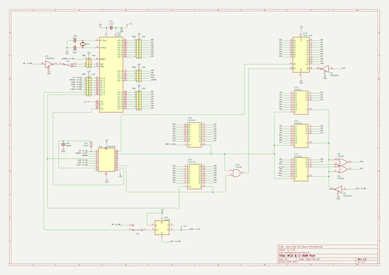
The main and sub processors share a single 8 KB work RAM, and two processors cannot use the same memory in the same instant. The A78-03 at 43 decides which one has it and holds the other still on its WAIT pin until the RAM is free, so neither processor ever reads a wrong byte, it just loses the time. A jumper, JP3, adds a second wait of the same kind on the main processor, which picks up an extra T-state whenever it reaches into the video RAM on the wrong phase of the 3 MHz clock, enough to slow a block copy into video RAM from 21 to 22 T-states per byte. Emulation gives both processors instant memory and stalls neither of them. The core reproduces the A78-03 and the JP3 wait and drives the real WAIT pin on each processor, so they contend for memory the way the board makes them. The other FPGA core models both waits as well. Below are the main CPU and the shared work RAM with its arbiter, from schematic extraction:
The main processor interrupt does not come from the raster. It comes from the protection microcontroller, which takes the vertical blank itself and, as the first thing its handler does, pulses one of its port pins. It only does so once the main program has written a handshake byte into their shared RAM, which the program does just before it first enables interrupts and takes away again on its error paths. A 74LS74 at 30 latches the rising edge of that pulse, and the acknowledge cycle forces the shared RAM's address to the one cell where the program keeps its interrupt vector. The interrupt therefore lands 93 microcontroller cycles after the vertical blank rather than on it. Measured from the PCB, it lands roughly 96 µs after the vertical blank, and the core takes it between 95 and 96 µs with x6801u4. Emulation takes it well over twice as late, typically about 235 µs after the vertical blank. The other FPGA core latches the same rising edge, but starts the microcontroller's handler from the sub processor's interrupt rather than the vertical blank, covered below.
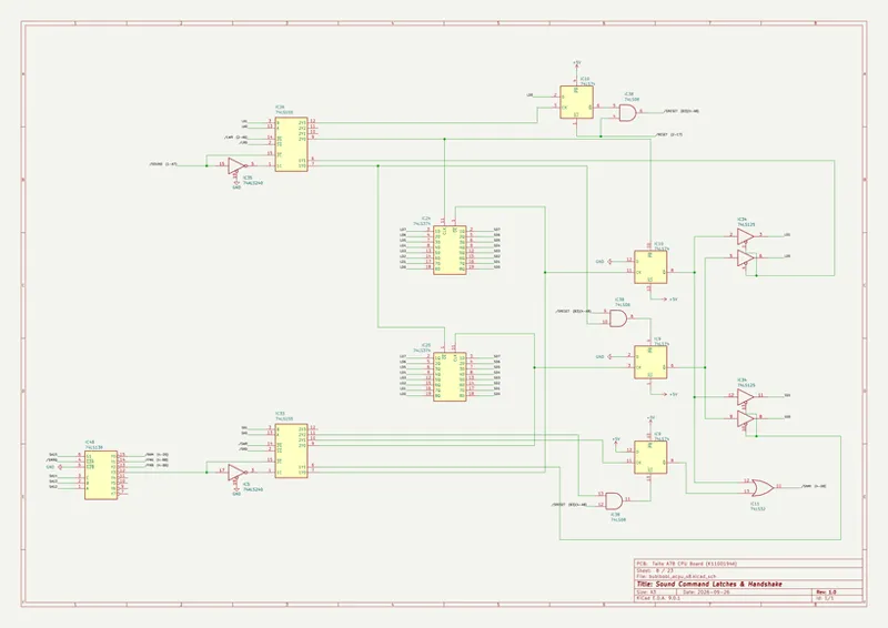
The main processor starts first and holds the sub processor and the microcontroller in reset through its 74LS273 control latch until it writes it, and the sound processor has a reset of its own that the main program pulses at boot and at every game over, which the other FPGA core ignores for this game. From then on the two Z80s watch each other. The sub processor bumps a heartbeat byte on every one of its interrupts and the main program reboots the board if that byte stops moving for 180 frames, while the sub processor wipes part of the work RAM if the main processor's frame counter stalls. A 74LS393 watchdog sits behind all of it and resets the board after 128 frames without a kick. The other FPGA core instead holds the main processor in reset for another 128 frames and leaves the sound section running. Below are the sub CPU with its reset and watchdog, and the control latch, from schematic extraction:
Graphics Pipeline:
Everything drawn on screen is an object. The program keeps a list of four-byte records at the top of the video RAM, each carrying a Y position, a code byte, an X position and an attribute byte, and rewrites it from work RAM every vertical blank. The code byte says whether a record is a 16 by 16 object or one of the tall 16 by 256 columns the playfield is built from, and a column can chain onto the X position of the one before it, which is how the program lays a whole strip of background across the screen. The same byte points at the block of tile entries the record is drawn from, which sit in the same video RAM. There is no tilemap and no scroll register, only the list and the tiles it points at.
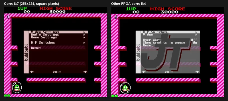
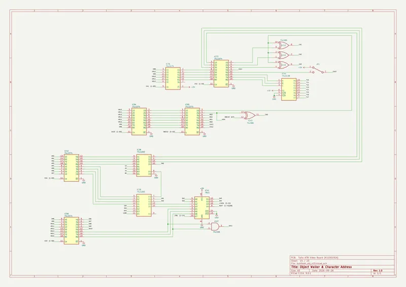
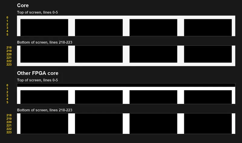
The board works out what to draw one line at a time. A two-bit step counter decoded by a 74LS139 at 40 latches each record's Y, code, X and attribute in turn, and two 74LS283 adders at 28 and 29 add that Y to the current line. The top four bits of the sum, three bits of the code byte and the vertical blank address the A71-25, which decides whether the record touches this line and which band of its tile entries to fetch. A column is never skipped, while a 16 by 16 object only draws in the band that lands on it. Emulation has no equivalent to any of that. It runs a loop once per frame and draws every object whole into a frame buffer. The core walks the list once per scanline straight out of the live video RAM, forms the same sum and reads the real A71-25 to decide each record's row, the way the adders and the PROM do. The other FPGA core also walks the list per line and reads the real A71-25, but a line late, so everything sits one line lower than on the board, the first visible line is always blank and the last is never shown. Below are the object walker and the character address, from schematic extraction, along with the same screen from the core and the other FPGA core:
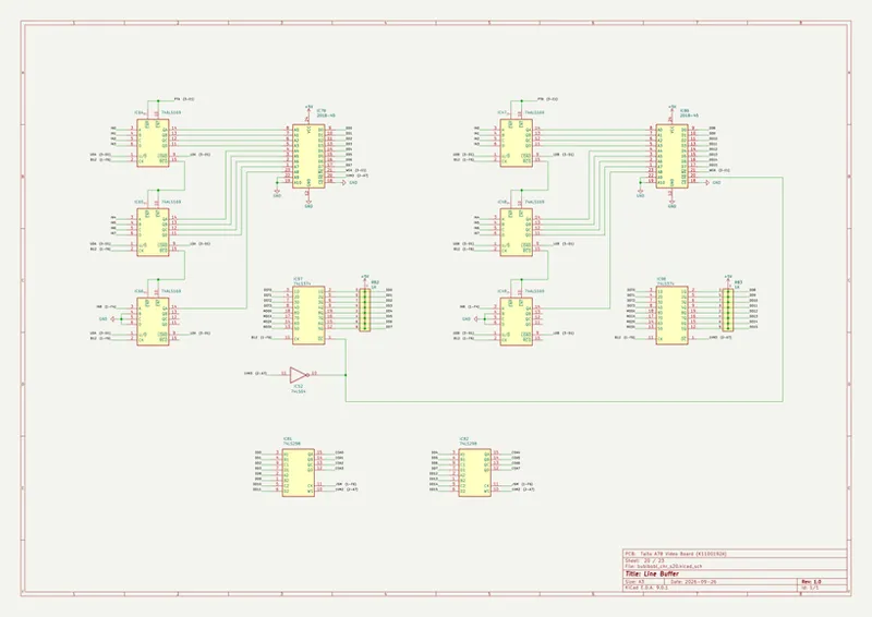
Each tile entry carries a tile code, a four-bit color bank and a flip bit for each axis, and the record's attribute byte picks one of eight pairs of character ROM sockets through a 74LS138 at 44, six of them stuffed. Every read returns sixteen bits, four pixels at four bits each, and four 74LS194 shift registers at 4 through 7 clock them out through an inverting 74LS158 at 53. A 74LS20 at 24 flags the pen that means transparent so it is never written, and the finished pixels land in one of two 2018 line buffers at 79 and 80, which swap roles every line while a pair of 74LS298s at 81 and 82 clock the displayed one out at 6 MHz into the palette. Below is the line buffer, from schematic extraction:
The palette is RAM, and fifteen of each entry's sixteen bits reach three Taito PC040DA hybrids, five bits per gun. Each hybrid is a six-bit binary ladder with its lowest input tied to ground, and because that ladder is linear, a linear expansion in the core is exact rather than an approximation. Emulation and the other FPGA core take four bits per gun and drop the fifth. The core drives all five, so every color it shows is the same as emulation's or slightly darker, about 3 percent at full intensity, where the board has a step emulation rounds away. The game never sets the fifth bits in play, so the difference is small on screen and clear only on the palette RAM test, which writes every bit. Below is a comparison of the palette between emulation and the core:
Blanking works the same way at the hybrids. The control latch's /BLACK line reaches all three PC040DAs and forces every gun to 0 V from the moment it is written. Emulation checks it once per frame and fills the whole screen with palette entry 255, a color the game uses as a backdrop and changes during play. The core forces black after the palette read on every pixel, as the hybrids do, and so does the other FPGA core. It clears uncovered pixels to palette entry 15 instead of 255, though, so the backdrop flashes the game drives through entries 239 and 255 never show. Below is the color output and its hybrid DACs, from schematic extraction:
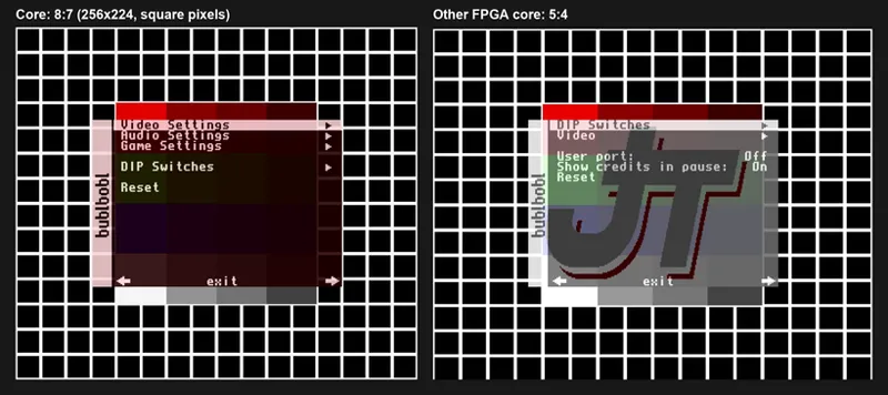
The sync comes out of the same counter chain as everything else, a 29 pixel horizontal sync after a 51 pixel front porch and an 8 line vertical sync after a 16 line front porch. Emulation does not generate sync at all; it hands a finished frame to the display. The core drives sync where the board does. The other FPGA core starts its horizontal sync 10 pixels early and runs it for 27 pixels, and starts its vertical sync 2 lines early and holds it for only 3 lines. Together with its objects landing one line low, that leaves the test mode grid cut off and wrapped. Below is the test mode grid on the core and the other FPGA core:
Protection MCU:
The A78-01 is a Motorola MC6801U4 sitting in a socket at 17, silkscreened PS4, running from its own 4 MHz crystal, which it divides by four internally for a 1 MHz bus. The other FPGA core configures its microcontroller as a plain MC6801 rather than the U4 and clocks it from the system clock gated with the three Z80s, so it stops whenever they wait on memory. The main processor holds the microcontroller in reset through the control latch until the main program is ready to start it. Every player input and both DIP switch banks are wired only to the microcontroller, through a 74LS253 matrix no Z80 can reach, so the game only ever sees its controls and settings through the copies the microcontroller writes into their shared RAM once per frame. It also works out the direction and distance of up to seven enemies against each player, runs a 600 frame countdown, counts the EXTEND letter, and fires the main Z80's interrupt described above. On the board all of that starts from the vertical blank. The other FPGA core starts it from the sub processor's interrupt instead, so the microcontroller misses every vertical blank while the sub processor boots with interrupts off.
The shared RAM is a 2 KB 2016 at 16, and the A78-04 at 12 controls which side, the main processor or the microcontroller, can read and write it at any given moment. It is a registered PAL with four buried registers on the 6 MHz clock, it reads no address line at all, and it gives the microcontroller the RAM for one clock at a time, only while the main processor is not using it. Emulation and the other FPGA core complete each microcontroller access instantly on the strobe and never let the two sides contend for the RAM, and the other FPGA core allocates only 1 KB of the 2 KB 2016. The core models the A78-04's registers and makes the microcontroller wait its turn the way the board does. This keeps the order of the two sides' accesses the same as the board's, which is what decides whether the main processor reads the EXTEND counter before or after the microcontroller updates it. Below are the microcontroller and its shared RAM port, from schematic extraction:
The main program does not trust the microcontroller to be there. At boot it waits for a sign-on byte the microcontroller writes about 46 ms after release, once it has summed its own ROM, then checks the result and stops on a PS4 SUM ERROR if it is wrong. That sign-on byte is checked again at 27 places in the program, eleven of them through disguised pointer arithmetic, and most of the failure paths quietly corrupt the game rather than stop it. The real mask program has to run from the first frame.
The processor underneath it is x6801u4, our own MC6801U4. It is a fully synchronous, cycle-accurate Verilog implementation, every state change landing on the clock edge under a clock enable. Every E cycle of every instruction, interrupt and reset sequence matches the datasheet's cycle-by-cycle table in address, read or write and data, dummy reads included, and it covers all 220 opcodes, the 192 bytes of on-die RAM, the six-function timer, the serial interface, the four ports with their handshake lines, and all eight operating modes. A test bench of 3,431 self-checking tests passes in full. In this core it divides an exact 4 MHz enable by four, so every frame is exactly 16,896 microcontroller cycles. Emulation may not match the part that closely.
Audio Section:
The board's audio comes from a YM2203 and a YM3526, both at 3 MHz, and the core runs our own implementation of each, x2203 for the YM2203 and x3812 for the YM3526. x2203 covers the OPN feature set, three four operator FM channels with the eight connection algorithms and a three channel sound generator, and x3812 is our OPL2, which drops to the sine-only subset that is the YM3526 when its wave-select bit is left clear, as this program always leaves it. Both are fully synchronous, taking their timing from a clock enable off the master clock, and both pass their output through a model of the YM3014 each one feeds on the board.
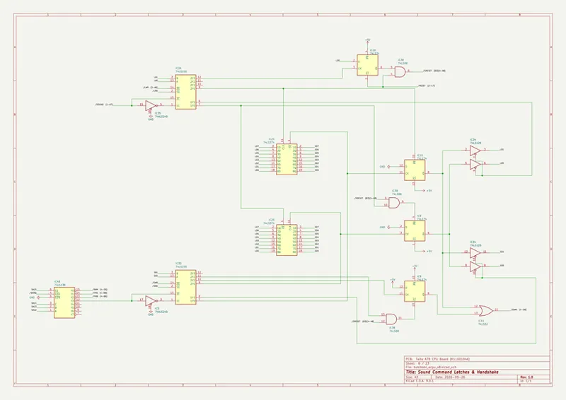
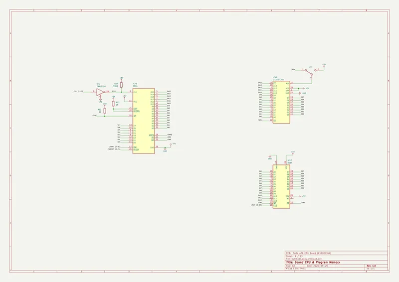
All of the music plays on the YM3526, and the sound effects play on the YM2203's FM channels. The YM2203's two timers pace both, one driving the music and re-tuned by tempo commands, the other driving the effects, and both start at about 60.56 Hz, so the music keeps its own time rather than the video output at 59.185 Hz. The SSG from the YM2203 is wired into the mix, but nothing the game sends in play gives it any volume; the only tone it ever makes is a test-mode A4. Below are the sound command latches and the sound CPU, from schematic extraction:
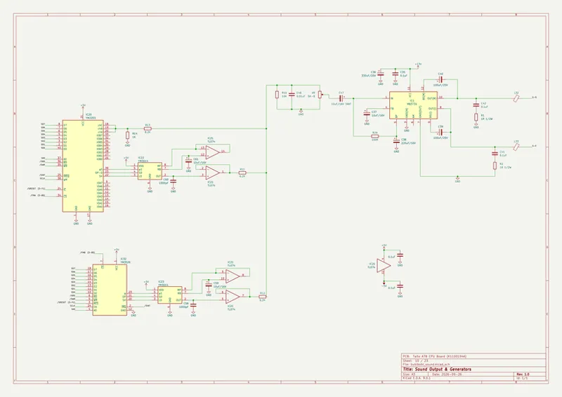
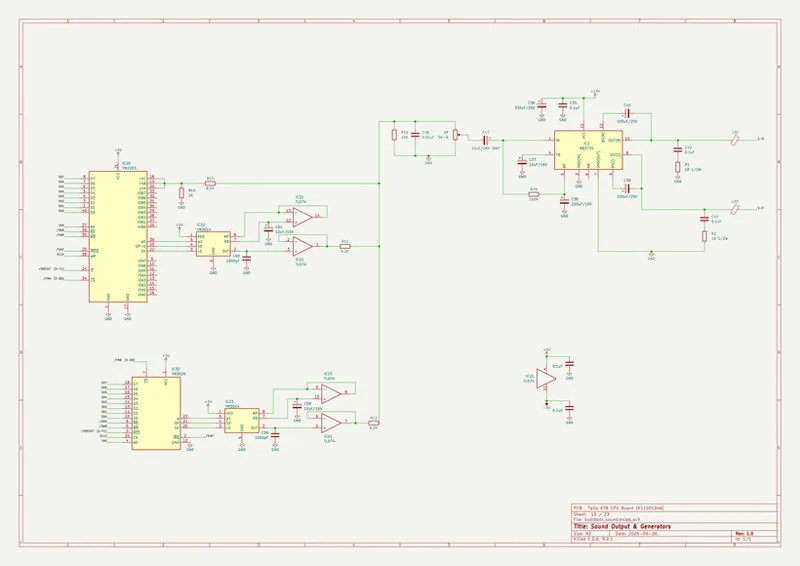
Everything after the two DACs is analog and summed passively. Each YM3014 feeds a TL074 unity follower into a 6.2K resistor, the joined SSG outputs come in through 8.2K, and the three meet at one node carrying a 0.01 µF capacitor, the only part on the board that shapes the audio band, rolling off gently from about 11.5 kHz. Two coupling capacitors take out everything below about 12 Hz, and the MB3731 limits softly only as it nears full output. Emulation mixes the two chips digitally at fixed levels and models none of the audio output path, and the other FPGA core applies only a fixed low-pass. The core runs the board's chain stage by stage off the schematic, so the PCB filter setting takes about half a decibel at 5 kHz and a little over three at 12 kHz, as the schematic's values call for. Below is the sound generator and output chain, from schematic extraction, along with audio playback from the board and the core:
Game Speed:
The frame output itself is the same on the board, in emulation and in the core: 384 by 264 at 6 MHz, 59.1856 Hz, 101,376 main processor T-states and 16,896 microcontroller cycles every frame, all exact divisions of the core's master clock. What decides how fast the game plays is what fits inside that frame. The main processor only runs the frame's game tasks if it has finished the previous frame's work; if it has not, that interrupt takes a short path and the game slows for a frame. Which frames lag depends on how long each processor is held on WAIT and on where in the frame the interrupt lands. Emulation stalls neither processor and takes the interrupt more than twice as late. The core stalls both where the board does and takes the interrupt where the board does, so it plays at the same speed as the PCB, slowing on the same frames. The other FPGA core stalls both processors too, but its speed has never matched the PCB. Two reports of it drifting from the board were closed without a fix, and the reporter confirmed afterward that the slowdown still differed from the first round.
Taito's own manual calls the EXTEND letter completely random, and to a player it is. Underneath, the microcontroller adds one to a counter on every vertical blank, lag frames included, wrapping every six, and the main program reads that counter once as each letter bubble enters the screen. Each new letter lands two places after the last, one more for every lag frame, five more for every HURRY-UP banner, and one either way depending on whether the main program's read lands before or after the microcontroller's update. No player can steer any of that, which is why it plays as chance. It also means the letters are decided by timing rather than drawn at random, so a core that keeps the board's timing turns up the same letters as the board, and this one does. The other FPGA core's microcontroller misses the vertical blanks while the sub processor boots, so its count starts behind the board's, and its instant shared RAM access changes which side of the update the read lands on.
The special items work the same way, and they are not random either. The game counts about thirty kinds of event in work RAM, bubbles blown, jumps, water kills, HURRY-UP banners, letters popped and names entered among them, and at the start of every round it places the first item in a fixed 54-entry table whose counter has reached its threshold, with the thresholds set by the difficulty rank. Those counters survive game over and carry straight into the next credit, and are only cleared when the attract demo runs through to the high score table or the board resets. Several of the counted events and the item timers run on game frames, so they only line up if the game runs at the right speed. The core never clears RAM between games and keeps no save state, so item placement, the memory carried between credits, the EXTEND letters and the game speed all match the PCB. Below is footage of the core and the PCB running side by side:
Core Options:
The MiSTer core includes video settings for aspect ratio, vertical scaling and cropping, scandoubler effects, and H/V positioning and sync adjustments.
Audio settings provide separate OPN FM, OPN SSG and OPL toggles, each with its own volume control, and a filter selector that switches the board's own output chain in or out. Arcade dip switches are directly accessible from the OSD. Game settings include per-player auto-fire on either button or both with adjustable rates, mapping options for Player 1 and Player 2, and a synced mapping mode that mirrors Player 1's layout to Player 2.
Cheats are accessible from the OSD and cover starting area and round, game mode, game ending, invincibility, hit anywhere, power-up mode, fireballs and jump height, along with per-player infinite lives, movement speed, fire speed, bubble range, bubble type and head power. Starting Area and Starting Round together start the game on any round from 1 to 100, and Mode starts every game straight into Super mode when selected. Ending picks which ending plays when round 100 is cleared, whatever the number of players or the mode. Bad plays the one-player false ending, Good plays the two-player ending with its hint screen, and True plays the Super mode ending. Every cheat works on all four sets. The program checksums itself while it runs, and every patch to it falls inside a checked range, so once any cheat that patches the program is turned on, the core bypasses those checks until reset.
The Pocket core provides auto-fire on either button or both at adjustable rates, and carries invincibility, infinite lives, hit anywhere, power-up mode, fireballs, bubble range and bubble type. It has no audio settings and plays without the board filter. Arcade dip switches available on Pocket are Language, Difficulty, Extend, and Players.
The core supports the four official romsets, Bubble Bobble (Japan, Ver 0.1), Bubble Bobble (Japan, Ver 0.0), Bubble Bobble (US, Ver 5.1), and Bubble Bobble (US, Ver 1.0).
History, Gameplay, and Regional Information:
Bubble Bobble was designed by Fukio Mitsuji and released in Japan in early September 1986. It was sold as a complete board and, from late September, as a conversion kit for Scramble Formation. The staff roll credits Mitsuji with game design and characters, Ichiro Fujisue and Nishiyori with the programming, Tadashi Kimijima of Taito's in-house sound team ZUNTATA with the music, Naoko Yoshida with the instructions, and Katsujiro Fujimoto and Seigo Sakamoto with the hardware. In a 1988 interview with BEEP!, the team said they set out to make a game girls could enjoy. They found bubbles on a list of more than a hundred things girls like to draw, and chose dinosaurs over spiked robots for the ridges down their backs. Game Machine's table cabinet chart placed it second behind Arkanoid in the 1 November 1986 issue, and it finished fifth in the magazine's table cabinet ranking for 1987.
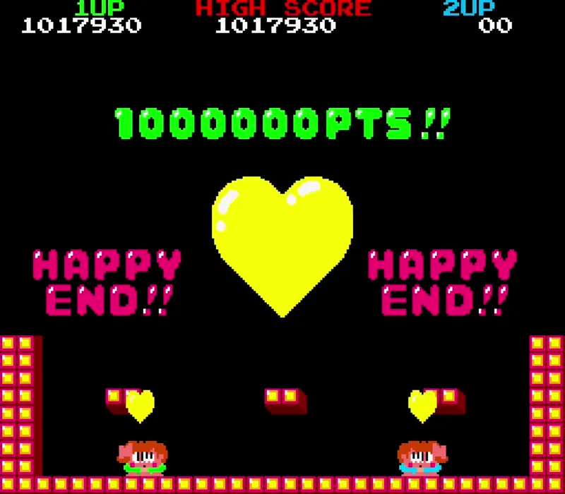
Bub and Bob are two boys turned into bubble dragons, heading down through the Cave of Monsters to rescue their girlfriends Betty and Patty. They trap enemies in bubbles and pop them, and each popped enemy drops food that scores more when several go at once. Take too long and HURRY-UP flashes, the enemies turn angry, and an invincible Skel-Monsta comes after the players. Special items turn up on the event counters described earlier, and letter bubbles spell out EXTEND, which clears the round and adds a life. Taito's manual adds that popping three to seven trapped enemies at once releases one to five letters, doubled with two players, and a second player can join at any time.
Round 100 is held by Super Drunk, and reaching round 20, 30, 40 or 50 without losing a life opens a door to a secret room. A single player who beats round 100 is told it is not the true ending and to come back with a friend, then is zapped back to a round between 50 and 85. Two players get an ending with a hint screen, and the true ending belongs to Super mode. Taito's manual tells the story only at the true ending, warns of a false ending that holds a clue, and recommends playing with two. Overall, Bubble Bobble is a game built to be played with a friend.
The title screen hides three eight-input codes, which Taito printed on a sticker in 1987. Start, Jump, Bubble, Left, Right, Jump, Start, Right begins a Super game. Bubble, Jump, Bubble, Jump, Bubble, Jump, Right, Start begins the Original Game, which opens the secret room doors without a no-miss run. Left, Jump, Left, Start, Left, Bubble, Left, Start powers the players up from the first round and keeps the power-ups through every death. The Original Game code also works as a copy check. On a board that fails it, the game prints DEAD COPY GAME !!! and sets 100 credits.
The four sets follow the build dates in their ROMs. Japan Ver 0.0 is dated 18 August 1986, US Ver 1.0 26 August, Japan Ver 0.1 4 September and US Ver 5.1 8 November. The US sets credit Taito America Corporation and state that the game is licensed to Romstar for the US. A dip switch picks the language. Japanese, Taito's factory setting, opens with a notice that the game is for use in Japan only and explains the rules in Japanese, while English prints the rules in English. US Ver 5.1 also asks for NORMAL or SUPER at the start of every game, where the other sets keep Super mode behind the title screen code.
Bubble Bobble was converted to nearly every home system of its day. Firebird's home computer versions arrived in 1987, where the Commodore 64 release won a Zzap!64 Gold Medal and the ZX Spectrum release a Crash Smash. Taito's own Famicom Disk System version followed in October 1987, and Final Bubble Bobble reached the Master System in 1988. The arcade original returned in Taito Legends and Taito Memories in 2005, and through Hamster's Arcade Archives for modern consoles in 2016 and 2022.
Updates:
Bubble Bobble follows the release of KiKi KaiKai, and other Taito releases are planned for next Tuesday. The Toaplan 1 updates for both MiSTerFPGA and the Analogue Pocket will also be released this week.
Rally Bike / Dash Yarou! (1987)
Truxton / Tatsujin (1988)
Demon's World / Horror Story (1989)
Hellfire (1989)
Fire Shark / Same! Same! Same! (1989)
Zero Wing (1989)
Out Zone (1990)
Vimana (1991)
The files are carried by update_all on MiSTerFPGA and by pupdate on the Analogue Pocket. Please allow the updaters time to sync before pulling them down. The files are attached to this post as well if you would rather install manually.
Disclaimer: All product names, trademarks, and registered trademarks mentioned are the property of their respective owners. "Analogue", "Analogue Pocket", "OpenFPGA", "MiSTer", "MiSTerFPGA", "Taito", "Taito America", "Romstar", "Bubble Bobble", "KiKi KaiKai", "Scramble Formation", "Arkanoid", "ZUNTATA", "Toaplan", "Game Machine", "BEEP!", "Firebird", "Commodore", "Sinclair", "ZX Spectrum", "Zzap!64", "Crash", "Nintendo", "Famicom", "Sega", "Master System", "Hamster", "Arcade Archives", "Zilog", "Motorola", "Yamaha", "Fujitsu", "Texas Instruments", "MMI", and all derivative works are trademarks, registered trademarks, or copyrighted materials of their respective holders. Use of these names does not imply endorsement or association with this post. All rights reserved to their respective owners. This post is for educational and research purposes only.Comments (8)
Frankly superb write up and in depth detail as usual 👏🏼
Hi Coin-Op collection team - high quality write up and delivery as normal - do you think you could add an additional folder to the main Arcade folder on mister so we can have all your teams arcade game easy access and in one place so like Arcade/CoC/mras and Arcade/CoC/Alternatives/game/mra alternatives - I like these cores as they are high quality compared to some of the other stuff being released of late and it will make it easier to go find them all :) just a suggestion to perhaps add to update_all
I believe someone set this up recently. See below: Add this to your Downloader.ini [hyp36rmax/MisterFPGA-DownloaderPLUS/coinop-collection] db_url = https://raw.githubusercontent.com/hyp36rmax/MisterFPGA-DownloaderPLUS/main/dist/coinop-collection/coinop-collection.json.zip
Is this intended as an improved implementation over jtbubl (any specific known issues?) or more as a CoC-framework (with added features) version? Just curious as I couldn't find any mention of the differences between this and the JT implementation? Obviously I'm a big Bubble Bobble fan, so lots of love for all the care put into this release and all the lovely geeky bits in the post <3
The post clearly states the differences. It's a reverse engineered version from the PCB and matches it 1:1. Audio is different, this core does not lose sync to the pcb, item placement, extend, and respawn when you start over follow the PCB behavior.
Is high score saving implemented?
this just loosed my sphincter a little, [redacted] yeah! immaculate work
Bad language makes for bad feelings.