
















Coin-Op Collection Presents: KiKi KaiKai (Taito A85)
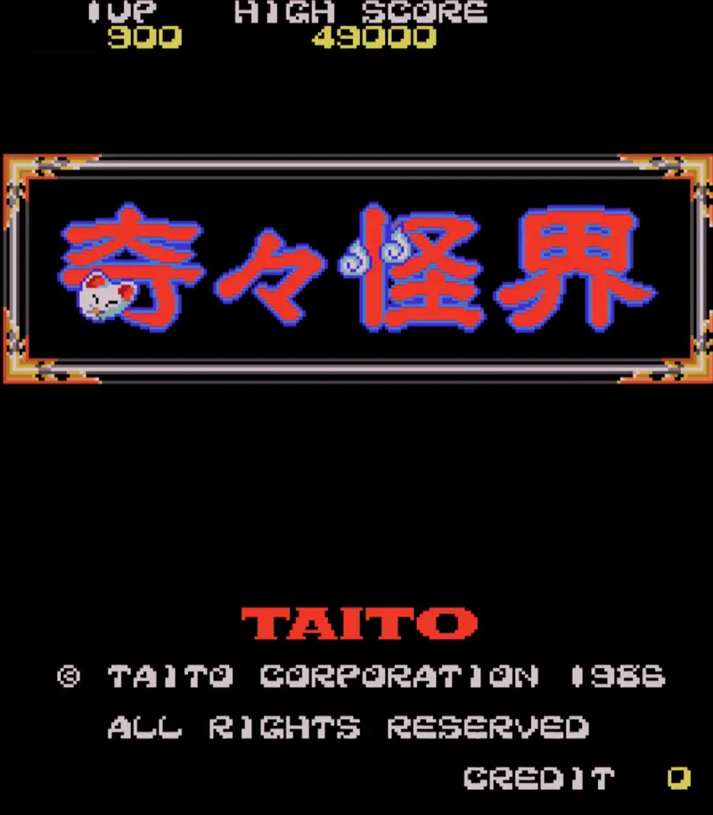
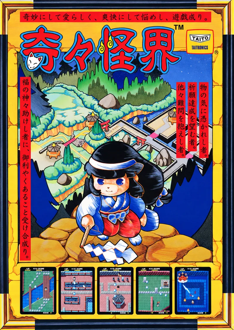
Today's release for the Analogue Pocket and MiSTerFPGA platforms is KiKi KaiKai, a 1986 Taito arcade game built on the A85 architecture. KiKi KaiKai is an overhead action game where Sayo-chan, a miko serving at a Shinto shrine, fights her way through eight scenes of yokai to recover the Seven Lucky Gods.
The hardware was designed by Taito's Kumagaya laboratory. The board renders a 192-entry object list that sits in the same RAM the game code runs from, and two PAL devices step a chain of counters, latches and shift registers through that list once per line, filling a line buffer a line ahead of the display. There is no tilemap present; the entire graphics pipeline is made up of sprites. The hardware consists of two Z80s, a protection microcontroller labeled PS4, one YM2203 and the graphics pipeline.
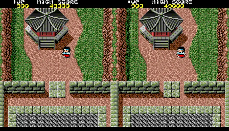
This post covers a technical overview of KiKi KaiKai, the work the board required, and the game itself. Below is gameplay of KiKi KaiKai captured from my PCB:
Overview:
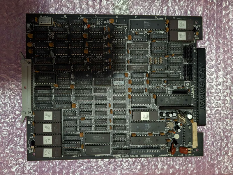
KiKi KaiKai runs on Taito's A85 hardware (PCB K1100195A / J1100079A), driven by a Zilog Z80B at 6 MHz working through a fixed window at the bottom of the map and a banked window above it paged over six banks. A second Z80B at 6 MHz handles sound, and the two processors share the same screen and work RAM rather than passing a latch back and forth. A Taito A85-01 sits alongside them, a socketed Motorola MC6801U4 silkscreened PS4 running an internal mask program, which owns the coin and player inputs, drives the PC050CM coin module and leaves its results in a RAM it shares with the main processor.
The audio is generated by a YM2203C at 3 MHz through a YM3014 serial DAC, two unity-gain follower stages in a JRC4556 and an MB3731 bridge-tied power amplifier. Both DIP switch banks hang off the YM2203C's own parallel ports rather than a port of either processor, and the FM and SSG legs are summed passively at a single node. Audio output is mono.
Every clock on the board descends from a single 24 MHz oscillator, halved to 12 MHz and again to 6 MHz for the pixel clock and both Z80s, with the horizontal counter's first divider stage halving that again to 3 MHz for the microcontroller and the YM2203C.
The video system outputs 256x224. There is no CRTC on this PCB which was common for the time. The raster comes out of the counter chain itself, giving a 6 MHz pixel clock with an HTOTAL of 384 and a VTOTAL of 264. Each 64.00 µs line splits into 256 active pixels (42.67 µs), a 51 pixel front porch (8.50 µs), a 29 pixel sync (4.83 µs) and a 48 pixel back porch (8.00 µs) for a 15.625 kHz horizontal rate, while each 16.90 ms frame splits into 224 active lines (14.34 ms), a 16 line front porch (1.02 ms), an 8 line sync (0.51 ms) and a 16 line back porch (1.02 ms) for a 59.1856 Hz vertical rate. These measurements were taken from the PCB.
Graphics are sprites and nothing else. The board carries 24 KB of static RAM across six devices and every one of them is spoken for, so there is nowhere for a tilemap to live. Backgrounds are drawn as tall 16x256 sprite columns, and what reads as background is a pixel no sprite covered. The object list and the table of 8x8 tile indices it points at both sit in the work RAM the two Z80s share, and the video section reaches them through a port arbitrated by one of the board's six PAL devices. A second PAL sequences the walk through that list and a third drives the character fetch, with 74LS161 and 74LS163 counters, 74LS283 adders and four 74LS194 shift registers between them handling the position arithmetic and serializing the pixels. Characters are 8x8 at 4bpp out of 256 KB of ROM across four MBM27C512 devices. Finished pixels land in one of two 2 KB line buffers, which change hands at every line boundary so one fills while the other is displayed.
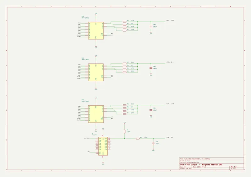
The palette is three 63S141AN PROMs, one per gun, each driving a four-resistor ladder of 2.2K, 1K, 470 and 220 ohms straight to its video pin. That gives 256 entries in 12-bit RGB, four bits per channel, of which this game addresses 128.
Development Challenges:
Main CPU and Sound CPU:
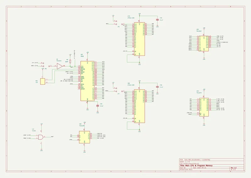
The board has a single block of RAM holding the screen data and the game's working variables, and both Z80s need it. Two processors cannot read the same memory in the same instant, so the A85-05 at 10D decides who has it, and whichever one loses the round is held still. The PAL raises a wait line, a 74F08 at 11E puts it on the main Z80's WAIT pin, and a second gate in the same package does the same for the sound Z80 through JP4. A Z80 with WAIT asserted freezes partway through its memory cycle and picks up again when the line releases, so neither processor ever reads a wrong byte, it just loses the time. A pair of 74F74s at 10E stretches the sound CPU's accesses to the sound chip the same way. This is the first place the core and current emulation differ. Emulation hands both processors instant memory and never stalls either one. The core reproduces the A85-05, bus-owner latch included, and drives the real WAIT pin, so the two processors contend for that RAM the way they do on the board. Below are the main CPU and sound CPU sheets, traced from the PCB:
That RAM is two 8K by 8 devices at 1C and 3C standing side by side on one thirteen-bit address bus, which makes the array sixteen bits wide. The video section reads both halves at once and takes two object bytes per access, which is how it keeps up with the beam. The CPUs only ever want one byte at a time, so their A0 never reaches that address bus; the A85-05 turns it into a pair of chip selects, SCNCS0 and SCNCS1, that pick which half answers. The main processor sees the first 10 KB of the array at C000 and the sound processor sees all 16 KB of it at 8000, so the 6 KB above what the main processor can reach is the sound side's private working memory. Nothing on the board divides that region, a 74LS139 at 9E looks at two address lines and hands the whole of it over on one output. This is also why the graphics can be built out of the same RAM the game is running in.
The two Z80 processors never pass a sound latch back and forth either. Everything one says to the other is written into that shared RAM and read back out of it. The main program is twice what a Z80 can address, so the board keeps the half that always has to be resident in a fixed window at the bottom of the map and pages the rest through a banked window above it, six banks deep. The A85-06 at 16G does the steering, and the bank number lives in a 74LS273 at 15H alongside the character bank select, the character fetch mode lines and two palette bank lines. That latch is clocked from a register page decoded by a 74LS139 at 16E on two address lines and nothing else, so its four registers repeat every 32 bytes through the whole of F000 to F7FF. Emulation maps four single addresses there, which is what this program happens to use rather than what the board answers to.
Graphics Pipeline:
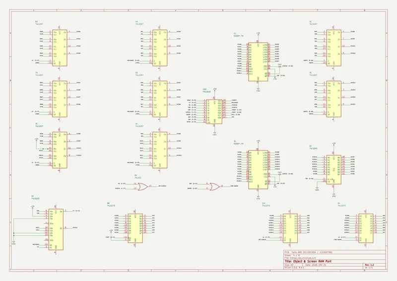
Everything drawn on screen is an object. The board keeps a list of 192 entries in the work RAM the two Z80s share, four bytes each, carrying a Y position, a control byte and an X position, and a chain of counters at 6E, 7C and 8E steps through that list. The control byte says whether the entry is a 16 by 16 object or one of the tall 16 by 256 columns the backgrounds are built from, and it also points at the block of tile indices the object is drawn from, which sits a little further along in the same RAM. Nothing here is a tilemap. There is no scroll register to write and no separate video memory to fill, only the list and the tiles it points at.
The board works out what to draw one line at a time. A 74LS374 at 9B catches the object's Y position as it comes off the screen RAM, and two 74LS283 adders at 10B and 11B add that to the current vertical counter, one handling the low four bits and the other the top four with the carry passed between them. The eight bit sum goes straight into the A85-03 at 7B, which decides from it whether the object touches the line being drawn and, if it does, which row of the object to fetch. Emulation has no equivalent to any of that. It runs a loop once per frame and draws every object whole, top to bottom, into a frame buffer. The core walks all 192 entries once per scanline and recomputes the row inside each object every line, the way the adders do. Below are the screen RAM port and the object pipeline, traced from the PCB:
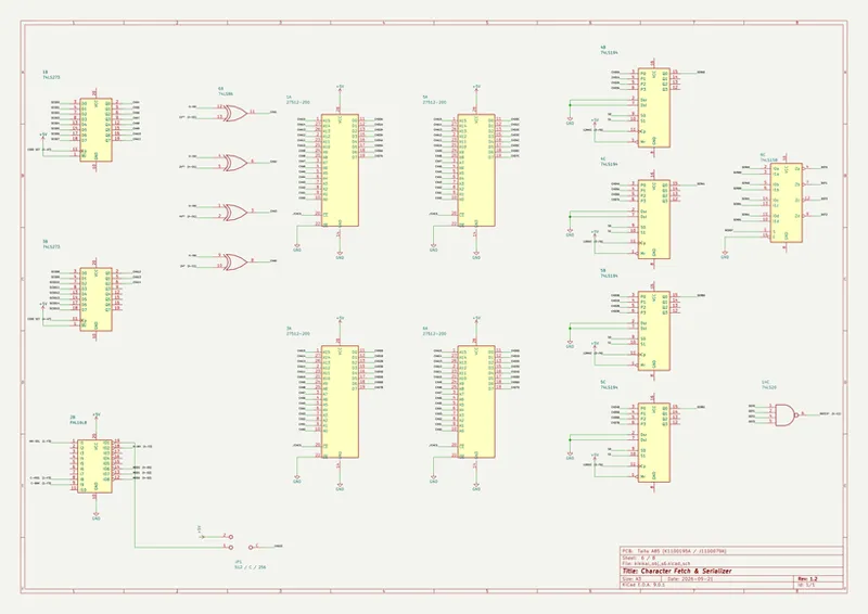
Once a row is chosen, two 74LS273s at 1B and 3B build the character ROM address out of the tile index, and the A85-04 at 2B supplies its top address bit and the fetch mode lines. The four character ROMs hand their bytes to four 74LS194 shift registers at 4B, 4C, 5B and 5C, which clock the pixels out at 12 MHz, and a 74LS158 at 6C merges those streams into the finished four bit pixel, which is an index into a group of sixteen colors rather than a color itself. A 74LS20 at 14C watches all four bits at once and flags the all ones case, which the hardware treats as transparent, so a pixel whose four bits are all set is never written at all. Below is the character fetch and serializer:
Those pixels do not go to the screen, they go into one of two line buffers at 12F and 15F, each a 2K SRAM holding one line while the other one is being displayed. The write address is not counted up from zero. A pair of 74ALS169 counters per buffer is parallel loaded with the object's X position off the HP bus and counts on from there, and because that is an eight bit counter it rolls over from 255 back to 0, so an object hanging off the edge of the screen is split and drawn at the other side rather than cut short. Emulation clips those pixels and loses them. The core wraps them the way the counters do, so the object comes back on at the opposite edge. Three multiplexers at 14D, 15D and 16D hand every control line for the two buffers across to the opposite chip on each line, so the two swap roles once per line rather than at some position partway across it, and a pair of 74LS298s at 11F and 16F select whichever buffer is the displayed one and clock its contents out at 6 MHz into the palette PROMs.
Screen flip is two different mechanisms working on two axes. Vertically, eight 74LS86 gates XOR the vertical counter and turn the picture over. Horizontally there is no XOR anywhere; the flip line reaches the up and down pins of the line buffer address counters through the 14D multiplexer, so the buffer being displayed counts backwards while the buffer being written always counts forwards. The program drives that line from the Display Flip switch, and in a cocktail cabinet it turns the screen over between player one and player two. Emulation implements neither mechanism and draws the picture one way up whatever the switch says. The core drives both, so the screen inverts on the switch and turns over between players the way the board does. Below is the line buffer:
The three palette PROMs at the end of that chain each drive four outputs into a ladder of 2.2K, 1K, 470 and 220 ohms, and all four meet at one node with a 180 pF capacitor before running straight to the video pin. Those values are not a binary ladder. Their conductances stand at 1, 2.2, 4.68 and 10 where a proper ladder would give 1, 2, 4 and 8, so the top bit is about a quarter heavier than it should be, and the node settles at the conductance weighted average of whatever the four outputs are driving. Code 8 lands at 143 out of 255 where an even ramp would put it at 136, and code 1 lands at 14 where an even ramp would put it at 17. Emulation assumes the same four resistors but adds four pre-rounded per bit constants rather than solving the divider. The core solves the network off the schematic and carries the sixteen levels the ladder actually produces, so the two agree at fourteen of the sixteen levels and part company by one count at the other two. Below is the color output and its weighted resistor DAC:
The site those PROMs sit in is drawn for a larger part than the one fitted. It carries ten address lines and the top two come from the same latch that holds the bank number, so the board is laid out for four palette banks. The part actually fitted is a 256 by 4 and supplies one of them. Nothing stands between the three ladders and the video pins either, no blanking gate and no buffer, so blanking on this board is a matter of what gets written into the line buffer rather than a signal that cuts the picture off. Below is an example of the color output from emulation, the core, and minimal difference in the palette:
Protection MCU:
The A85-01 is a Motorola MC6801U4 sitting in a socket at 8H, silkscreened PS4, running four kilobytes of mask ROM. It is not a co-processor in the ordinary sense. It owns the coin inputs and both players' controls, it works the coin mechanisms, the lockouts and the counters through the PC050CM module beside it, and it hands everything it gathers to the main program through a two kilobyte RAM the two of them share. It also carries a share of the game logic, collision handling among it, which is why the board will not play without it.
The MCU reaches only the first 256 bytes of that two kilobyte RAM, and the limit is physical rather than a convention. A 74LS157 at 10G has its three top address inputs on the MCU side tied to ground, so the upper bits can never be anything but zero, and the firmware agrees: the highest address it ever presents is 01F1. The transfers are not memory cycles either. The MCU puts an address on port 4, puts data on port 3 and pulses a strobe on port 2, and the two directions are not timed alike. A write lands on the falling edge of that strobe. A read is not sampled until the strobe has risen again, one instruction later. The core models both edges separately, because getting them the same way round would have the data arriving a cycle before or after the hardware takes it.
None of that was knowable for a long time. The mask ROM inside the PS4 went undumped for the best part of four decades, so emulation first borrowed the microcontroller out of a bootleg board, which is a different part running a different program, and then replaced that with hand-written code standing in for what the real one was assumed to do. In January 2024 Raki dumped the firmware and released it, and the collision behavior the protection governs came right for the first time. Thanks to Raki, emulation and the core both run that firmware on a real processor, not a simulation of what it might have done. Below are the PS4 and the shared RAM port on the board:
The processor underneath it is x6801u4, our own MC6801U4. It is a fully synchronous, cycle-accurate Verilog implementation, every state change landing on the clock edge under a clock enable, with instruction timing taken from the cycle tables in the MC6801 Reference Manual rather than approximated. It covers all 82 instructions across the part's six addressing modes, the single chip mode this board runs in, the internal register file, the 192 bytes of on-die RAM, the parallel ports, the programmable timer with its free running counter and output compare, the serial interface, and the three level interrupt priority the part arbitrates between its non-maskable, external and internal sources. A 702 test bench covers the arithmetic unit, the ports, the timer, the serial interface and every instruction in the set.
Audio Section:
The board's audio comes from a YM2203C at 3 MHz and the core runs x2203, our own implementation of the chip. It covers the OPN feature set, three four operator FM channels with the eight connection algorithms and a YM2149 class three channel sound generator with its own noise, envelope and thirty two level logarithmic converter, along with channel three's multi frequency mode and its timer driven key on. One operator datapath is time multiplexed across all twelve operators every sampling period and the accumulator latches a single mono sample per pass. It is fully synchronous, taking its timing from a clock enable off the master clock, and it presents both the parallel sample stream and the serial output the board's own YM3014 is fed.
Two things about how the chip sits on this board are easy to miss. Its interrupt pin is an unconnected stub and the program loads both timers without ever starting them, so the vertical blank interrupt paces the music rather than the chip. Its reset pin is tied to the same latch bit that holds the sound processor in reset, so the chip is re-initialized every time the main program toggles that bit rather than only at power on. Emulation drives the two processors from that bit and leaves the sound chip alone. The core resets all three, the way the latch does.
Everything after the chip is analog and summed passively rather than mixed. The FM leg leaves through the serial DAC and two unity gain followers into a 10K resistor, the three sound generator outputs are strapped into a 1K load and then a 30K resistor, and the two meet at one node that weights them at 3.1 to 1. Neither op-amp section shapes anything, both are strict unity followers with no feedback resistor and no reactive component inside either loop, so there is no active filter on this board at all. The core models that chain off the sheet and runs it on the chip's own sample strobe, an exact divide of the master clock that lands every sample period on a whole number of system clocks.
The only remaining task is taking measurements with the spectrum analyzer and to address the PSG tone playback. Audio output is vastly improved but still needs minor work. Below is the sound generator and output chain, traced from the PCB, along with audio playback from the board and the core:
Core Options:
The MiSTer core includes video settings for aspect ratio, vertical scaling and cropping, scandoubler effects, and H/V positioning and sync adjustments. KiKi KaiKai runs vertically, so a screen rotation toggle is included for HDMI displays.
Audio settings provide separate OPN FM and OPN PSG toggles, each with its own volume control at 100, 125, 150 or 175 percent, and a filter selector that switches the board's own output chain in or out. Arcade dip switches are directly accessible from the OSD. Game settings include per-player auto-fire with adjustable rates, mapping options for Player 1 and Player 2, and a synced mapping mode that mirrors Player 1's layout to Player 2.
Cheats are accessible from the OSD and cover invincibility, infinite lives, the secret character, turnip replacement, and Bloody Demise. Bloody Demise enables a death scene that was cut from the game, where Sayo-chan falls to the ground and bleeds, replacing the death caused by Manuke's rod.
The Pocket core provides auto-fire with per-button targeting and adjustable rates, and carries the same cheat set. Arcade dip switches available on Pocket are Test Mode, Difficulty, Extend, and Number Match.
The core supports a single set, KiKi KaiKai (Japan).
History and Gameplay Information:
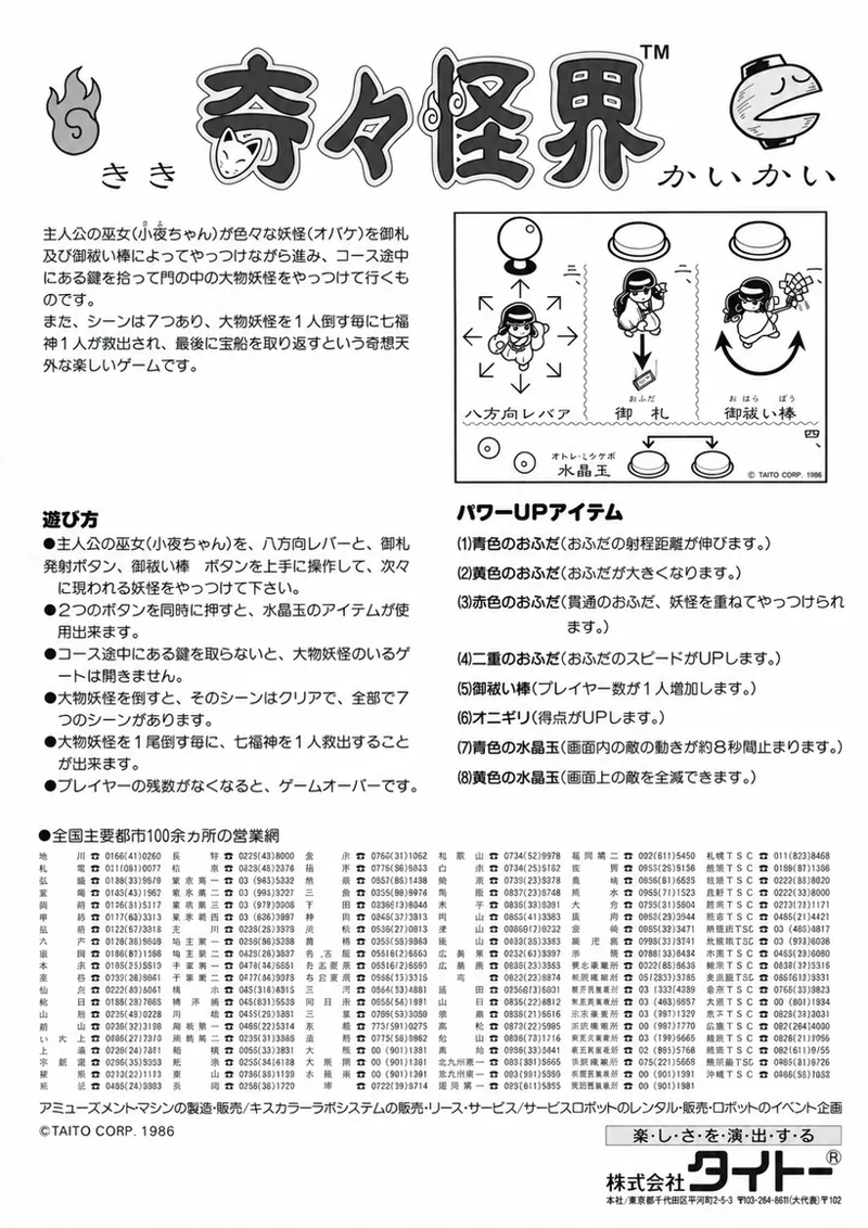
KiKi KaiKai was developed by the Kumagaya branch of Taito's Central Research Laboratory and released in Japan in October 1986. Flyers exist for a US release through Taito America, but no ROM dump of that version is known. Hisaya Yabusaki is credited with the planning and the original character concept, with Mikio Hatano directing, Kazutomo Ishida and Daisuke Sasaki programming, Nenko Nishimura and Kazuya Mikata on character design, Naoto Yagishita on sound effects, and music by Hisayoshi Ogura of Taito's in-house sound team ZUNTATA, a score built on children's songs and warabe-uta. Game Machine's table cabinet chart placed it second when it debuted in the 15 November 1986 issue, and it finished tenth in the magazine's operator-rated table cabinet ranking for 1987. The lab also signed its work. Take a game over and hold 1P Up, and the next title screen shows a small bear standing in a valley above the copyright line, a picture of the name Kumagaya, which is written with the characters for bear and valley. Inserting a coin while it is on screen starts the game with an extra life.
Sayo-chan fights to get the Seven Lucky Gods back from the yokai with two weapons. She throws ofuda, paper talismans, and swings the oharai-bo, a purification rod, at anything close. Her aim is locked to the direction she is moving with no way to strafe, only four ofuda can be in the air at once, and one hit costs a life. Each scene hides a key that has to be found before the boss gate will open, and sweeping the rod across lanterns, archways and stone statues turns up talisman upgrades and crystal balls, which are used by pressing both buttons together. A blue ball freezes everything on screen and a yellow one clears it, but the items are lost when Sayo-chan dies and neither item works against a boss.
Each of the first seven scenes ends in a yokai boss, running from an azukiarai and the thunder god Raidenou through a tengu, a mountain hag, a giant monk and a nine-tailed fox to Manuke, a tanuki who disguises himself as Sayo-chan and swings an oharai-bo of his own. Beating him frees the last of the gods, and just when the game looks finished an eighth scene opens with no boss at all, a looping maze where three scrolls have to be found among the jizo statues or the maze sends you back to the start. There is no continue. The only way to keep playing is the number match, a three digit roulette at game over that awards a credit if it lands on the last three digits of your score. Overall, KiKi KaiKai is a demanding game that rewards knowing where everything is hidden.
There was never an arcade sequel to KiKi KaiKai. The series continued at home, on the Famicom Disk System in 1987 and then MSX2, PC Engine and the Super Famicom, whose games reached the West as Pocky & Rocky with Manuke recast as Rocky, the player's ally. Altron's KiKi KaiKai Advance for the Game Boy Advance in 2001 went back to the arcade game, building its stages and Sayo-chan's moves on the arcade original with new items and sub-weapons added, and it was released in North America as Pocky & Rocky with Becky. The arcade original returned through Hamster's Arcade Archives for modern consoles in 2020.
Updates:
KiKi KaiKai is one of several releases planned over the course of this week, to include the Toaplan 1 updates for both platforms. The files are available on update_all for MiSTerFPGA and pupdate for the Analogue Pocket. Both can take an hour or more to sync, if you'd like to download the files here they are available.
Disclaimer: All product names, trademarks, and registered trademarks mentioned are the property of their respective owners. "Analogue", "Analogue Pocket", "OpenFPGA", "MiSTer", "MiSTerFPGA", "Taito", "KiKi KaiKai", "ZUNTATA", "Pocky & Rocky", "Hamster", "Arcade Archives", "Altron", "Game Machine", "Zilog", "Motorola", "Yamaha", "Fujitsu", "JRC", "MMI", "Nintendo", "Famicom", "Super Famicom", "Game Boy Advance", "Nintendo Switch", "MSX", "PC Engine", "PlayStation", and all derivative works are trademarks, registered trademarks, or copyrighted materials of their respective holders. Use of these names does not imply endorsement or association with this post. All rights reserved to their respective owners. This post is for educational and research purposes only.Comments (4)
Amazing job,
Awesome, thanks!
Great to have a proper release! Thanks team as always!
What a stunning write up! Thank you so much