





Fragmentation Envelope Add-on for Tacview
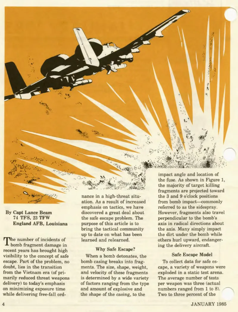
As it has been discussed in the past in other articles, weapon lethality is dictated not just by the blast wave, but by the high-velocity fragmentation pattern. In my many flights in various multi-player environment, I observed that a gap exists within the virtual flight simulation community: while weapon employment procedures are often well-practiced, there is a persistent lack of practical understanding regarding fuze settings and the necessary safe separation distances required during ordnance delivery, both after release and after detonation.
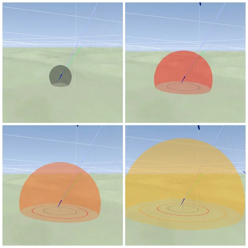
In order to try to address this, I have developed a new Fragmentation Envelope Add-on for Tacview. The fragmentation envelope modeled in this tool operates as a statistical bubble. Specifically, it represents the maximum volume the most dangerous fragments can reach following a detonation. It is important to understand the physical reality of this hazard. The density of fragments is extremely low at the outer boundaries of this bubble, but it is never zero. Because a single fragment strike can sever hydraulic lines, destroy an engine, or incapacitate a pilot, resulting in the loss of the aircraft, these boundaries must be treated as hard limits. When executing safe escape maneuvers, no chances should be taken with the fragmentation envelope.
How to Install and Activate
Unzip the downloaded archive to locate the Fragmentation Envelope folder.
Copy the entire folder into your Tacview add-ons directory: C:\ProgramData\Tacview\AddOns\.
Start Tacview. If the software is already running, navigate to the Settings (gear) menu and select Reload Lua Scripts (or use the shortcut Ctrl+R).
Navigate to the Settings menu, select Enable/Disable Add-ons, and tick Fragmentation Envelope so that it shows a check mark.
Access the Settings menu again and open the Fragmentation Envelope sub-menu to configure your display options, such as enabling the envelope for practice bombs or displaying the data legend.
I. Technical Methodology & Physics Engine
I.1 Data Sources
The physical parameters and hazard boundary distances used in this add-on are derived exclusively from primary, declassified military documents. The Probability of Incapacitation (PI) zones (specifically the 10%,and 0.1% boundaries) are extracted directly from the JFIRE 2007 and 2023. Fragment travel distances and ballistic data are validated against USAF Technical Orders, including TO SR1-1M-34 and the F-16A Weapons Delivery Manual (TO 1F-16A-34-1-1). The currently modeled warheads cover the Mk-82, Mk-83, and Mk-84 classes, with data tables validated for detonation altitudes ranging from 0 to 30,000 feet.
Important: it is a critical distinction that the fragmentation envelopes rendered by this add-on are calculated exclusively using real-world physical data and historical military references. They do not represent the internal damage model of DCS World. The simulator's native damage and fragmentation modeling is subject to regular changes and is highly criticized within the community for its inconsistencies. This tool visualizes where the real-world fragmentation hazard exists, providing a ground-truth pedagogical reference independent of how the host simulator resolves virtual damage.
I.2 Physics Engine and Flight Mechanics
To accurately simulate fragment flight paths, the underlying physics engine employs Newtonian kinematics within an International Standard Atmosphere (ISA) Troposphere model. Aerodynamic drag acceleration is calculated using the fragment's Ballistic Areal Density. Importantly, the mathematical simulation does not terminate upon ground impact, but instead, it runs to a strict fixed time limit of 35 seconds. This constant simulation time ensures the renderer correctly displays fragment positions in 3D space for airburst deliveries or over uneven terrain.
I.3 The "Worst-Case" Fragment Philosophy
As a first implementation, the add-on utilizes the static detonation assumption used in USAF Technical Orders models, treating the initial bomb velocity as 0 m/s. Consequently, the fragmentation envelope is calculated as a surface of revolution, creating a perfectly symmetrical volume around the vertical axis of the detonation. The system plots the trajectory of the "worst-case fragment," which is defined as the fragment possessing the highest initial velocity and the most favorable aerodynamic profile. For example, the worst-case fragment for a Mk-82 warhead is modeled mathematically as an elongated steel splinter measuring 0.40 m by 0.02 m by 0.006 m, with a mass of approximately 375 grams and an initial velocity reaching up to 2,400 m/s. By enforcing full revolution symmetry for this theoretical worst-case fragment, the model is deliberately conservative. This design parameter ensures that the rendered envelope never under-represents the physical hazard during mission analysis.
II. Architecture & Technical Use
II.1 Offline Data Pipeline and Runtime Efficiency
To ensure Tacview frame rates remain untouched during long or cluttred debriefs, the add-on is (at this stage) designed to execute zero physics simulations within the Tacview runtime environment. Instead, fragment positions have been rigorously pre-computed offline: the resulting data have been converted into standalone Lua lookup tables (eg: mk82_frag_model.lua). That's an easy way to adapt your model if you want to use other values than the ones that have been derived from existing docs.
During playback, the Lua add-on simply performs a fast natural cubic spline interpolation using these pre-computed tables. The data architecture stores seven distinct altitude layers spanning from sea level to 30,000 feet in 5,000-foot increments. At render time, the engine linearly interpolates between the two altitude layers that bracket the actual detonation altitude of the weapon.
II.2 Rendering and Performance Optimizations
Rendering simultaneous 3D fragmentation envelopes for a dense ripple release requires strict resource management to prevent visual stutter. I tried to implements several core performance optimizations. For example, detonations sharing the same weapon type, altitude bucket, and time step share a single vertex array, allowing one mathematical shape to serve an entire ripple.
II.3 Training Munition Integration
Effective range training requires understanding the lethal footprint of the simulated ordnance, not just the impact point. The add-on includes an option to display a notional frag envelope for inert and practice munitions. Within the internal weapon database, training rounds such as the BDU-33, BDU-45/50 or Mk-84 AIR TP are directly linked to the fragmentation models of their live-warhead analogues. By toggling the "Show Envelope for Practice Bombs" menu option, flight members can visualize the exact fragmentation hazard that a live weapon would have generated during the practice pass. This feature is kept disabled by default to ensure practice ranges remain decluttered unless the data is specifically required for the debrief.
III. Data Interpretation
III.1 3D Surface Color Mapping and Hazard Zones
The 3D surface dynamically changes color to represent the expanding fragment front's position relative to standardized Probability of Incapacitation (PI) boundaries. The inner boundary, colored dark grey, indicates the fragment front is inside the 10% PI limit. The envelope transitions to red between the 10% and 1% PI boundaries, and to orange between the 1% and 0.1% PI boundaries, the latter denoting the Danger Close threshold as defined in the JFIRE. Beyond the 0.1% PI boundary, the surface shifts to yellow and light yellow, representing the geometry out to the absolute maximum fragment range.
III.2 Ground Danger Circles (REDs) and Burst Modes
Projected directly onto the terrain are thin, concentric annular circles that represent Risk Estimate Distances (REDs). These terrain circles represent the 10% (grey), 1% (red), and 0.1% (orange) PI zones, along with a maximum range outer ring (yellow). The numerical distances for these rings are calibrated for a standing, unprotected person subjected to a surface or contact burst, mixing JFIRE 2027 and 2023 standards. For airburst deliveries, real-world danger distances increase by approximately 25%, but this is not yet taken into account in the current add-on.
III.3 Ground Snap Extrapolation and the Impact Marker
ACMI flight data recording behavior required an impact correction protocol to maintain spatial accuracy. Telemetry recordings consistently terminate a weapon's track up to one sample-step (≤ 0.15 seconds, or roughly 66 meters of travel) prior to actual ground impact, often leaving the final recorded coordinate suspended ~20 meters Above Ground Level (AGL) in Tacview. This is all the more visible in multi-player recordings where the small time differences prevent immediate detonation detection. To resolve this recording artifact, I decided to extrapolate the terminal velocity vector directly down to the Tacview terrain surface. This mathematically determined intersection is marked with a flat, spring-green cross (measuring 10 meters in span with 1-meter wide arms) representing the true estimated detonation point. Important detail: Tacview terrain precision (or rather imprecision) adds another level of uncertainty: weapons that are perfectly recorded as "destroyed" on their last time stamp can still appear above ground, while in reality they've hit the ground in DCS. The question of high rise buildings can also not be addressed.
III.4 Telemetry Legend and Overlay Interface
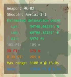
When a weapon is selected in the 3D viewport, the add-on can present a data legend anchored to the bottom corners of the screen.It panel provides explicit analytical telemetry for the selected ordnance. Displayed metrics include the weapon and warhead type, the deploying aircraft, the estimated detonation coordinates (Latitude, Longitude, Altitude), all three PI range boundaries, the maximum fragment range with its associated time, and the fragment apex height with its corresponding time. Due to current Lua API constraints within the host software, coordinates are exclusively formatted in decimal degrees, irrespective of the user's MGRS or DMS position format settings.
Conclusion & Roadmap
IV.1 Current Status
This first release of the Fragmentation Envelope Add-on establishes a functional, baseline capability for advanced flight simulation debriefings. By rendering a conservative, worst-case fragmentation volume alongside standard PI boundary rings, it already serves as a concrete pedagogical tool. It will allow you to directly evaluate weapon footprints, validate safe escape geometries, and visually represent Danger Close parameters during post-flight analysis.
IV.2 Next phases
I intend to sequentially increase physical fidelity. I a first time, I'll add more warheads to the fragmentation models, for example Mk-81 or BLU-109. When the data is available, I'll incorporate as well foreign bombs.
In the longer term, I'd like to transition from a purely safety-oriented visualization to a more realistic ballistic model. This phase will account for the dynamic delivery kinematics of the weapon, in particular the bomb's velocity vector at the moment of detonation. By incorporating the forward momentum of the weapon, the system would discard the symmetric surface of revolution and instead calculate and render an asymmetric "butterfly" fragmentation envelope.
Note: because the outputs of this add-on are derived from physics-based approximations and unclassified sources, a strict operational boundary must be recognized. This add-on is distributed exclusively for educational and pedagogical use within flight simulation environments. The rendered geometry is a notional visualization.
Comments (1)
Nice addition 👍🏾